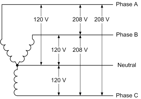
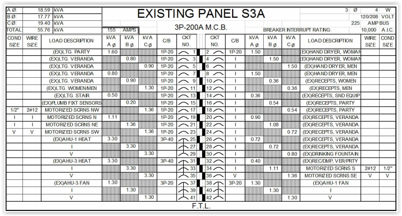
208 Volt Single Phase Wiring Diagram

We are wiring in a large ups system that requires input voltages of 208v single phase and outputs the same.
208 volt single phase wiring diagram. Now normally when dealing with 208220 voltage i expect to see two hots a ground and a neutral. In parts of the world 240v single phase 2 wire is the standard for homesheres more. If you are using this unit as an isolation transformer with a primary of 120 or 240 or 480 volts and the secondary of 1224 1632 or 2448 depending on the model use the wiring diagram located on the inside of the cover to the wiring compartment. Here is a picture gallery about 208v single phase wiring diagram complete with the description of the image please find the image you need.
The y in 208y120v refers to the neutral as the center of the y shaped power source. Single phase motors are used to power everything from fans to shop tools to air conditioners. 240v power is used in the us and parts of the world. 208v 3 phase power also goes by the names 208v 3 phase 4 wire and 208y120v.
This is because the motors single phase actually operates on the difference between the two 120 volt phases that comprise the residential 240 volt input. 3 phase 208v motor wiring diagram with 208v single phase wiring diagram image size 1021 x 500 px and to view image details please click the image. The 4 wire in 208v 3 phase 4 wire refers to the neutral as 4th wire. Buck boost transformer installation sheet revised on april 2011 by te.
Single phase motor wiring diagrams single voltage motor 208 230v. Residential power is usually in the form of 110 to 120 volts or 220 to 240 volts. Some motors allow both 120 volt and 240 volt wiring by providing a combination of wires for doing so. In the us 120 240v 1 phase 3 wire is the standard for homes and 240v 3 phase open delta is the standard for small buildings with large loads.
The input lugs are labeled like this. These are technically more accurate because they refer to the neutral. G l1 l2n the outputs are the exact same.


