240 Volt 3 Phase Wiring Diagram

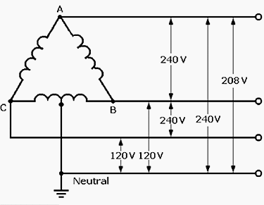
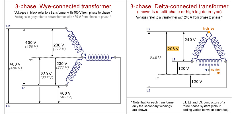
One is 208 240 volt singlephase 3 wire.
240 volt 3 phase wiring diagram. Now for the quick explanation of 240 220 volt house current. Cap it with a wire nut. 1 a black wire which is often known as the hot wire which carries the current in to the fixture. 480v 3 phase transformer wiring diagram step down tags to 120v.
480v to 240v transformer wiring diagram collections of 480 volt to 120 volt transformer wiring diagram image. Appliances which use straight 240 current such as electric water heaters or rotary phase converters also have three wires. Input power wiring diagrams option d input power wiring diagrams option d smart series b l o c k t e r m in a l above diagram depicts two different wiring configurations. To continue with your youtube experience please fill out the form below.
If there is a neutral wire in the conduit or cable supplying the motor it is unused for the motors three phase wiring. We have been receiving a large volume of requests from your network. 240 volt 3 wire split phase ballast bypass wiring instructions and diagram posted by sam t on 4272017 to led parking lot lights so you are trying to change to led lights with 240volt but now you have 2 hot wires and a neutralground coming out of the building. Hold the bare ends of the conductors together and twist on a wire nut.
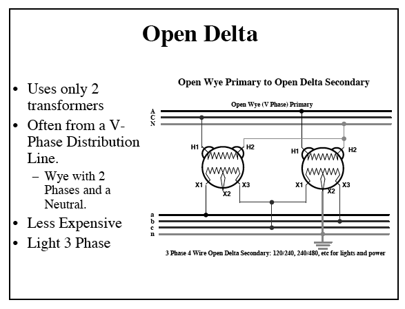
Note that lines rl1 and sl2 are connected through the circuit breaker to the appropriate terminal strips. For example use a red wire nut to connect two 12 gauge wires. In the us 120 240v 1 phase 3 wire is the standard for homes and 240v 3 phase open delta is the standard for small buildings with large loads. In parts of the world 240v single phase 2 wire is the standard for homesheres more.
240v power is used in the us and parts of the world. Sorry for the interruption.


