480 Volt Dayton 3 Phase Motor Wiring Diagram

Europe 3 Phase Motor Wiring Diagram 9 Wire Wiring

Europe 3 Phase Motor Wiring Diagram 9 Wire Wiring

Ac Motor Wiring Diagram 480 Vac Wiring Diagram

Ac Motor Wiring Diagram 480 Vac Wiring Diagram

240 480 Wiring Diagram Wiring Schematic Diagram 183

240 480 Wiring Diagram Wiring Schematic Diagram 183

240 480 Wiring Diagram Wiring Schematic Diagram 183

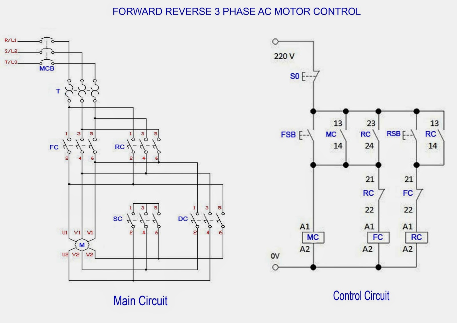
Three phase wiring diagrams always use wiring diagram supplied on motor nameplate.

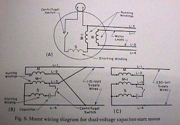
480 volt dayton 3 phase motor wiring diagram. For specific leeson motor connections go to their website and input the leeson catalog in the review box you will find connection data dimensions name plate data etc. Electric motor wire marking connections. Capacitor motor single phase wiring diagrams always use wiring diagram supplied on motor nameplate. W2 cj2 ui vi wi w2 cj2 ui vi wi a cow voltage y high voltage z t4 til t12 10 til t4 t5 ali l2.

Remove the motors wire connection cover being careful not to lose the four screws. Single three phase blower connection diagrams thermally protected. Single phase single voltage 4 lead induction generator. 173 to 1 ratio dual voltage or wye start delta run on low volts.

Industry wide the 480 volt 3 phase motor is the most common of all electric motors. 480v to 240v transformer wiring diagram collections of 480 volt to 120 volt transformer wiring diagram image. Three phase see below single voltage. Understanding the proper wiring methods can be a challenge if you are not familiar with some basic rules.

480v 3 phase transformer wiring diagram step down tags to 120v. Step down transformer 480v 120v wiring diagram trusted wiring. 480v to 120v transformer wiring diagram elegant 3 phase step down. Other wiring diagrams available.

Motor Wiring Installation Tips Electrical Construction

Motor Wiring Installation Tips Electrical Construction

12 Lead Motor Diagram Wiring Diagram

12 Lead Motor Diagram Wiring Diagram

How To Wire 3 Phase Electric

How To Wire 3 Phase Electric

Baldor 220 Volt Wiring Diagram Wiring Schematic Diagram

Baldor 220 Volt Wiring Diagram Wiring Schematic Diagram

Insides Of Emerson Motor Not Confirmed See Plan Only On

Insides Of Emerson Motor Not Confirmed See Plan Only On

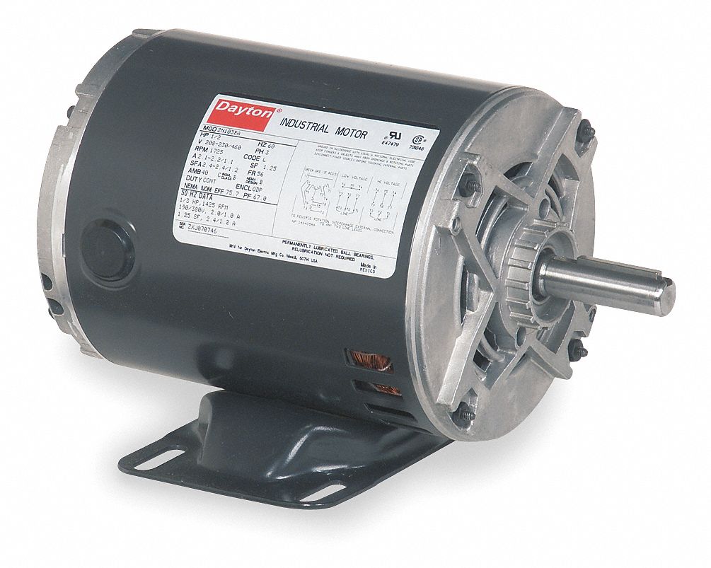
Dayton 1 Hp General Purpose Motor 3 Phase 1725 Nameplate Rpm

Dayton 1 Hp General Purpose Motor 3 Phase 1725 Nameplate Rpm

Ac Motor Wiring Diagram Wiring Diagram

Ac Motor Wiring Diagram Wiring Diagram

480 Volt 3 Phase Wiring Dayton Wiring Diagram

480 Volt 3 Phase Wiring Dayton Wiring Diagram

How To Install 3 Phase Timer

How To Install 3 Phase Timer

Identifying 230 And 460 Connections York Repair Inc

Identifying 230 And 460 Connections York Repair Inc

12 Wire Motor Wiring Diagram Wiring Schematic Diagram

12 Wire Motor Wiring Diagram Wiring Schematic Diagram

25 Hp General Purpose Motor 3 Phase 1765 Nameplate Rpm Voltage 230 460 Frame 284 6t

25 Hp General Purpose Motor 3 Phase 1765 Nameplate Rpm Voltage 230 460 Frame 284 6t

Practical Machinist Largest Manufacturing Technology Forum

Practical Machinist Largest Manufacturing Technology Forum

3 Phase 380 V To 3 Phase 230 V Electrical Engineering

3 Phase 380 V To 3 Phase 230 V Electrical Engineering

12 Lead Motor Diagram Wiring Diagram

12 Lead Motor Diagram Wiring Diagram

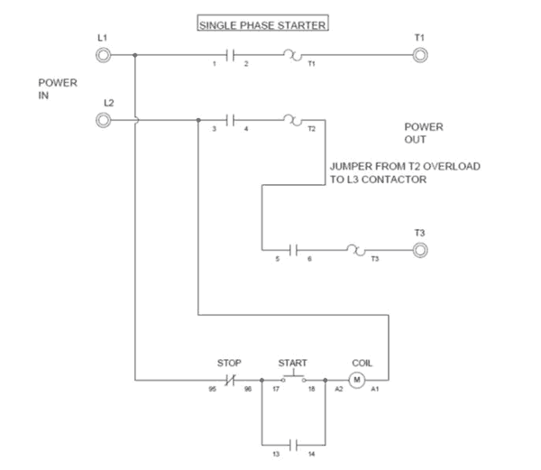
Wiring A Single Phase Motor Through A 3 Phase Contactor How

Wiring A Single Phase Motor Through A 3 Phase Contactor How

Motor Wiring Diagrams Groschopp

Motor Wiring Diagrams Groschopp

Reverse Baldor Single Phase Ac Motor Circuit Diagram

Reverse Baldor Single Phase Ac Motor Circuit Diagram

Source : pinterest.com

Popular Posts