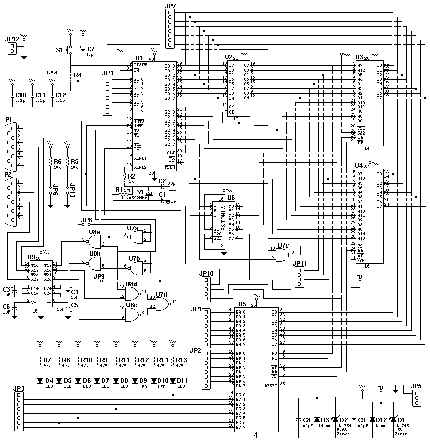
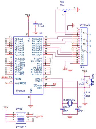
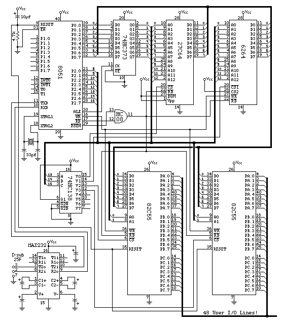
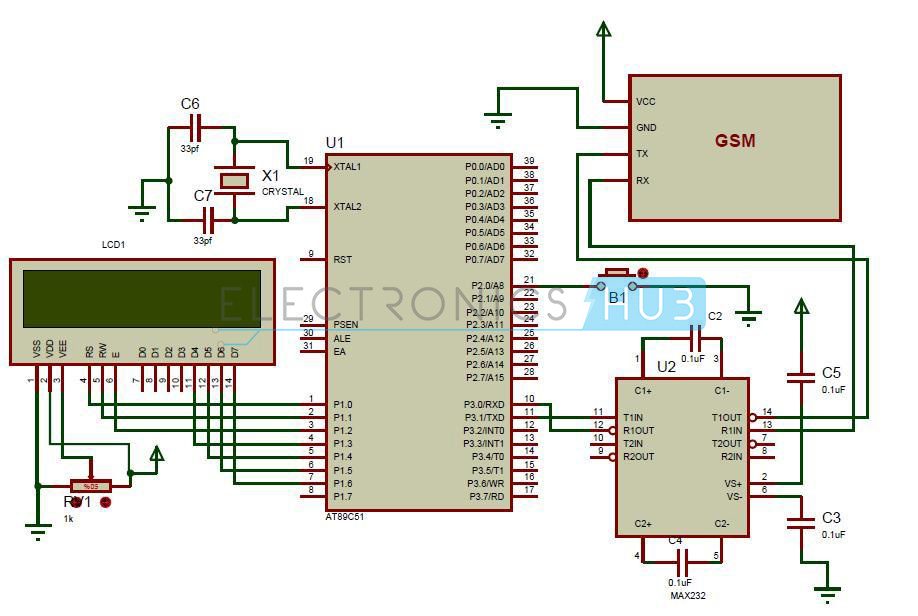
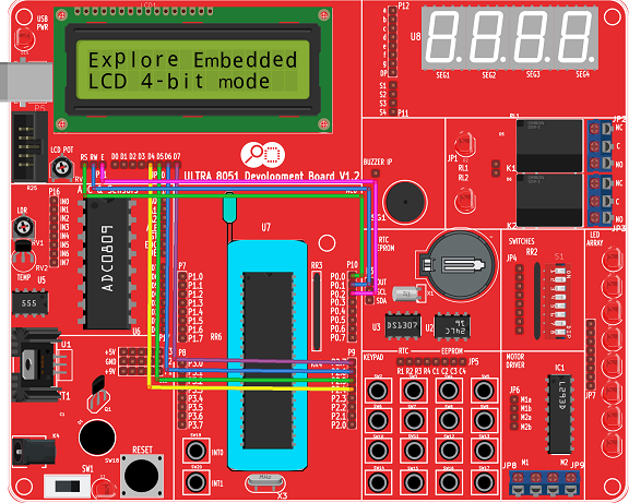
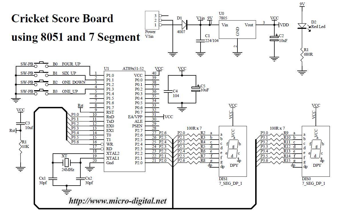
8051 Board Circuit Diagram
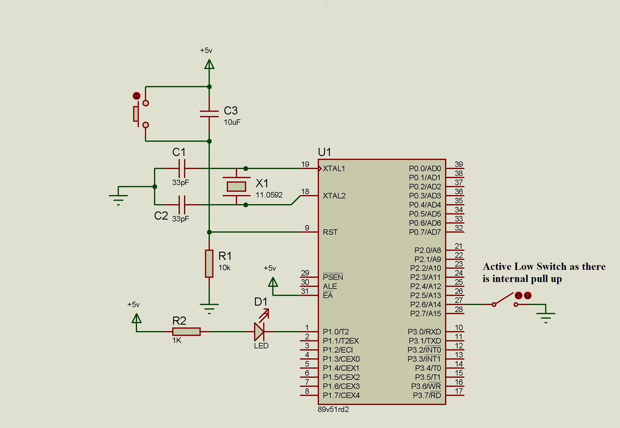
Interfacing stepper motor to 8051 microcontroller.
8051 board circuit diagram. It displays digits from 0 to 9 continuously with a predefined delay. This article is about interfacing stepper motor to 8051 microcontroller. Schematic drawing 8051 development board rev 5 use this high quality 600 dpi pdf for printing. This schematic is provided in the hope that it will be useful but without any warranty not even a warranty of merchantability or fitness for a particular purpose.
For this clock we can set the time at any instant. Burn the program to the 8051 microcontroller. I think this is the time. Such is well suited for students and budget limited experimenters alike.
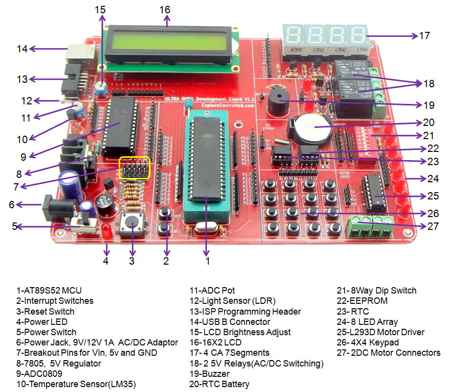
Here the clock can work in either 24 hour mode or 12 hour mode and the rtc chip is configured by programming 8051 controller. This is a simple circuit diagram of interfacing 7 segment to microcontroller. The board has at89s52 mcu8k flash memoryboard has on board power supply circuitrs232 port for serial communication with computer and other serial devicepower status ledredreset switch user switch and user led. Stepper motors are widely used in industrial medical consumer electronics application.
This delay using 8051 timers circuit is used in ultrasonic module applications embedded system applications where we want precise time delay. The circuit displays the time on lcd. Let us look in brief about the pin diagram of the 8051 microcontroller. Dirt cheap hardware is available for developing 8051 microcontroller applications.
Now give the connections as per the circuit diagrams. Bread board or pcb making circuit 162 lcd displaying text 44 keypad taking input potentiometer for setting lcd contrast crystal110592 mhz calculator with 8051 microcontroller circuit diagram. Lower four bits of 8051 port 1 are sccanning rows 44 keypad and. Port 1 of 8051 microcontroller is interfaced with 44 numeric keypad.
Many guys were asking here to show how to interface stepper motor to 8051 microcontroller. This is basic 8051 development board. The base board is fully open no peripheral is directly connected to the mcu breakout board. While giving the connections make sure that there is no direct supply connection from battery to the controller.
Switch on the board supply now the motor is at stationary condition.


