Block Diagram 555 Timer
Ic 555 Timer Working Pin Diagram Specifications Features

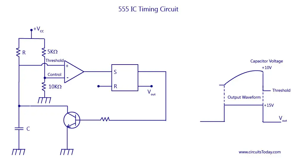
555 Timer Tutorial The Monostable Multivibrator

555 Timer And 555 Timer Working Electrical4u

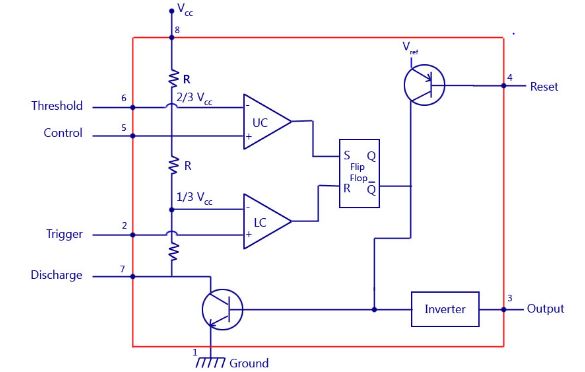
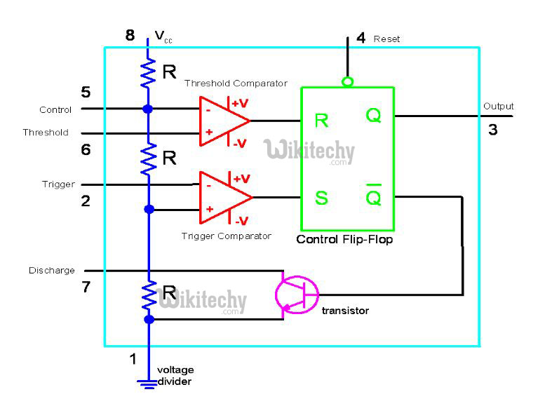
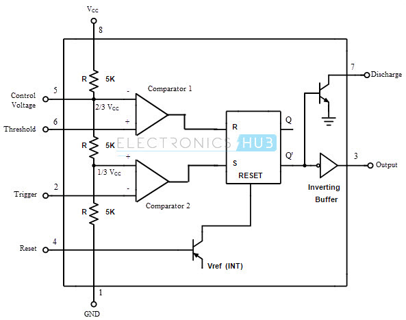
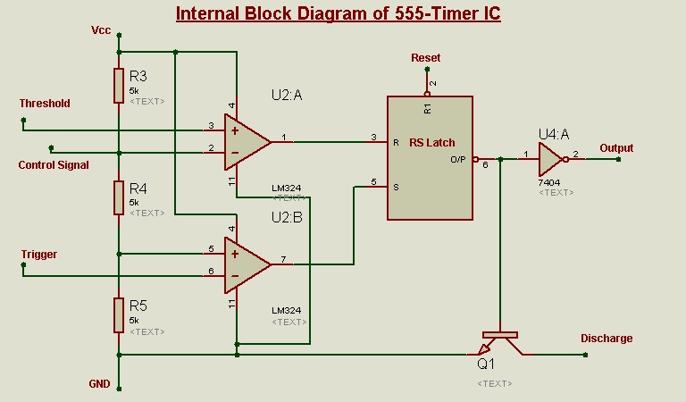
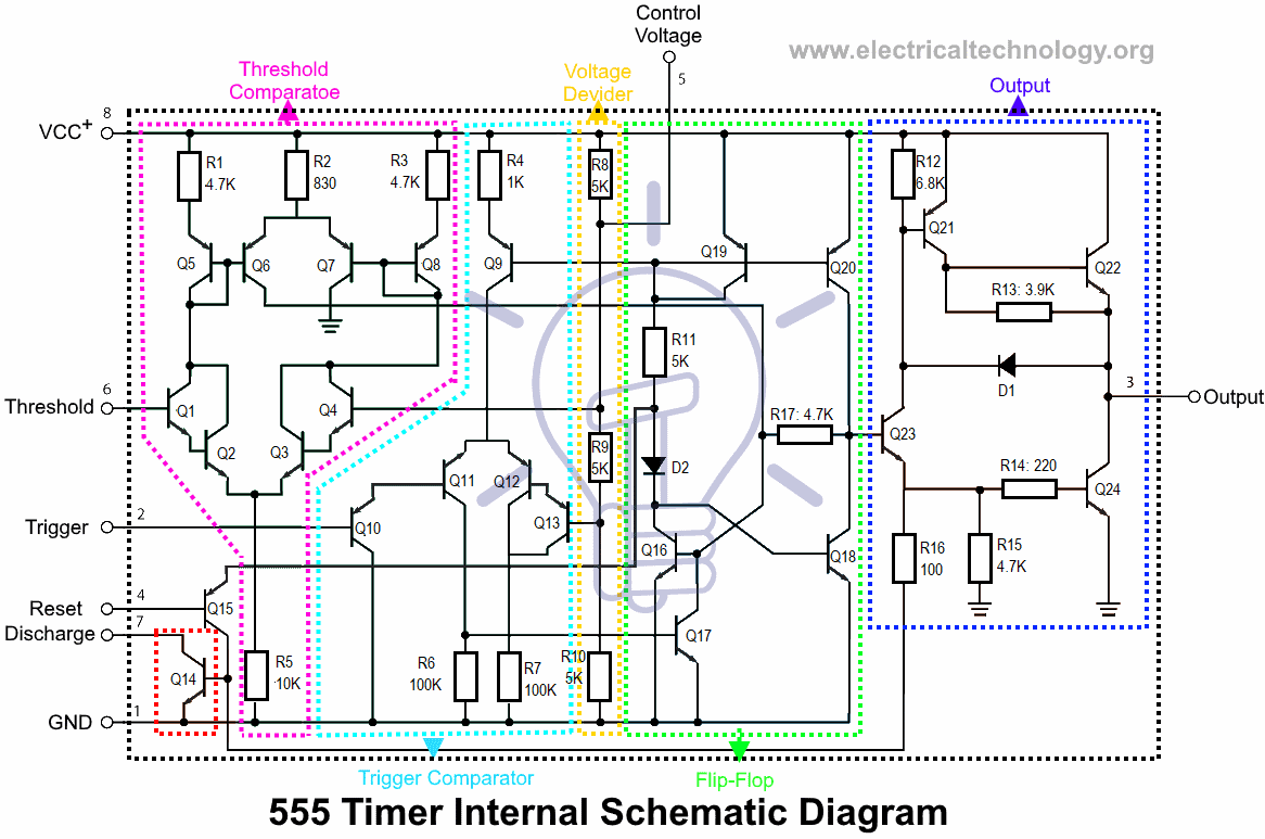
It consist of two comparators that means it has two op amps r s flip flop resistive network and also with two transistors.
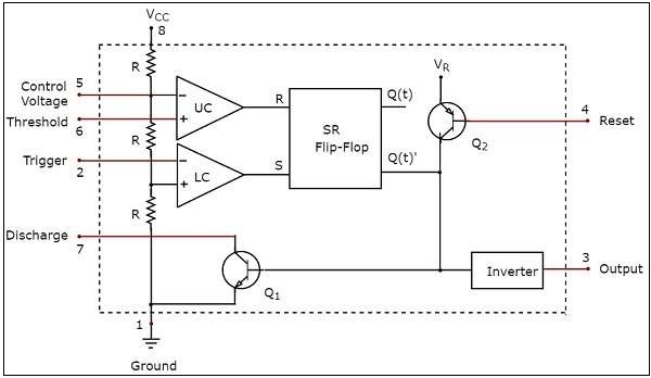
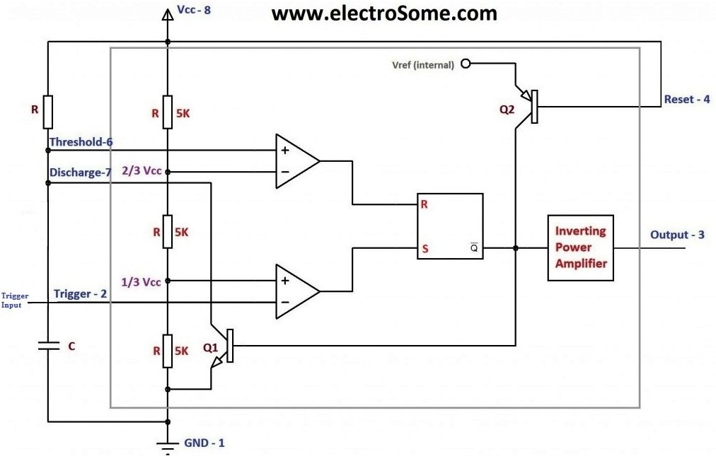
Block diagram 555 timer. The ic 555 timer can work with any supply voltage between 45 v and 16 v. The following image depicts the block diagram of the pwm based led dimmer using 555 timer ic. Comparator 2 compares the trigger voltage with a reference voltage 13 v cc volts. A 12v dc source is used to power the entire circuit including the 555 timer ic and the leds.
In this video the brief introduction to the 555 timer ic has been given and the pin diagram of 8 pin dip 555 ic and the internal block diagram of the 555. Ic 555 timer working. The 555 timer is used to generate a pwm signal with the help of a few passive components. 555 ic timer block diagram resistive network consists of three equal resistors and acts as a voltage divider.
Internal block diagram the 555 timer ic is an integrated circuit chip used in a variety of timer pulse generation and oscillator applications. However 555 is still the most popular. Ground the ground pin connects the 555 timer to the negative 0v supply rail. Pin diagram specifications.
Comparator 1 compares threshold voltage with a reference voltage 23 v cc volts. The various features of the ic 555 timer are. Features of ic 555 timer. This pin has no special function what so ever.
8power or vcc pin 1. Additional timing from microseconds through hours terminals are provided for triggering or resetting if. 555 timer block diagram pin 1. Variants consists of combining multiple chips on one board.
Depending on the manufacturer the standard 555 package includes 25 transistors 2 diodes and 15 resistors on a silicon chip installed in an 8 pin mini dual in line package dip 8. 72 functional block diagram. Now as shown in figure there are eight pins for a 555 timer ic namely 1ground. It can be used to produce time delays ranging from few microseconds to several hours.
Block diagram of 555 timer ic the following block diagram shows the 555 timer integrated circuit. 555 timer pin diagram and descriptions. The resistive network contains three equal resistors which will act as a voltage driver. Block diagram of led dimmer using 555.
Derivatives provide two 556 or four 558 timing circuits in one package. It is connected to ground as usual. A simplified block diagram representing the internal circuitry of the 555 timer is given below with a brief explanation of each of its connecting pins to help provide a clearer understanding of how it works.
555 Timer Ic Block Diagram Working Pin Out Configuration
555 Timer Led Flasher Block Diagram Of Ic 555 Timer By
555 Timer As An Astable And Monostable Multivibrator

555 Timer Block Diagram Electronic In 2019 Block Diagram

555 Timer Ic Basics And Working Principle With Applications
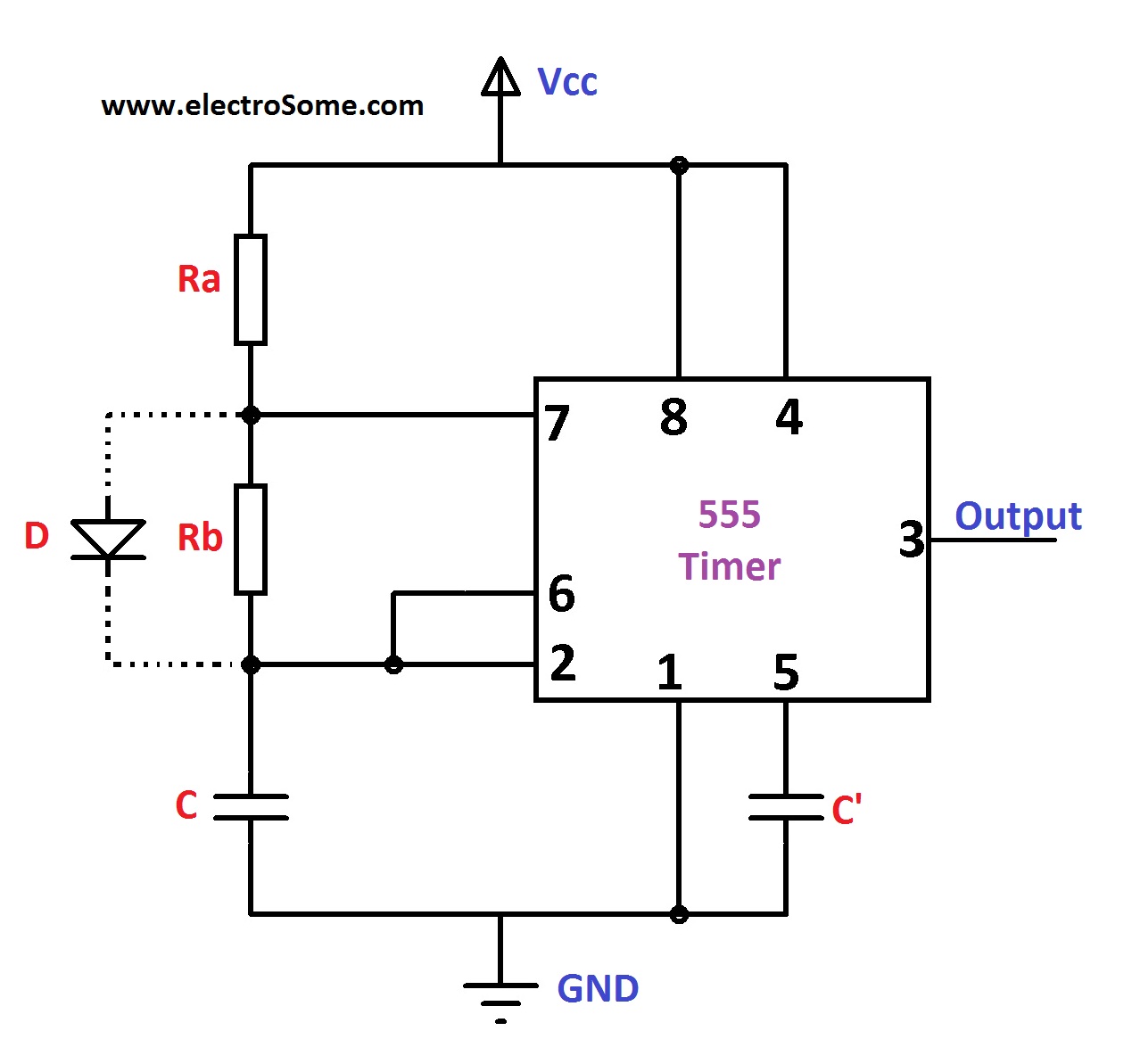
Astable Multivibrator Using 555 Timer

555 Timer Ic Wikipedia
555 Timer Circuits In Proteus Electronic Circuits And

Astable Multivibrator Using 555 Timer Block Diagram
555 Timer Tutorialspoint

Timer Ic 555 I Timing Circuit I Block Diagram I Features
Monstable Multivibrator Using 555 Timer
A 555 Timer Ic Tutorial
555 Timer Ic Types Construction Working Application

555 Timer Tutorial The Monostable Multivibrator
555 Timer Ic Internal Structure Working Pin Diagram And
555 Timer And Related Theory
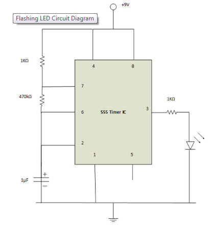
Making Of Flashing Blinking Led Circuit Diagram Using 555
