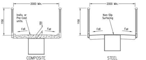
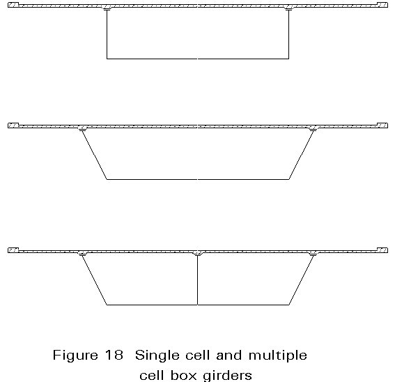
Box Girder Bridge Diagram

Part 3 for such structures.
Box girder bridge diagram. 24 2017 bridge masters bridge design. T girder bridges are generally very economical for spans of 1218 m with girder stem thickness usually varying from 35 to 55 cm controlled by the necessary spacing of reinforcements. Larger ones use trusses made from structural steel or box girders built from pre stressed concrete. Footpath on either side having spans as shown in fig.
After reading this article you will learn about the design of balanced cantilever bridges. For simply supported spans this limit is generally found to be nearly 10 metres and for continuous or balanced cantilever type. The box is typically rectangular or trapezoidal in cross section. Cantilever bridges can span relatively long distances while still appearing light and open.
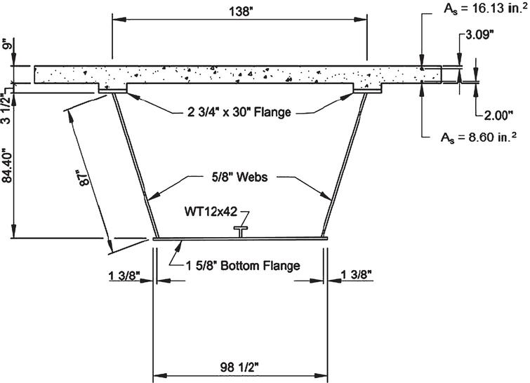
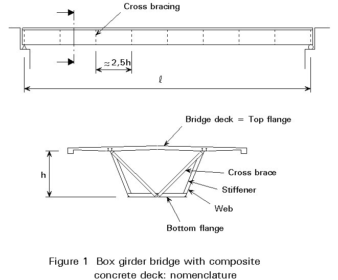
Slab and girder bridges are used when the economical span limit of solid slab bridges is exceeded. Citation neededthe term girder is often used interchangeably with beam in reference to bridge design. Box girder sections consist of top deck vertical web and bottom slab. Wisdot bridge manual chapter 24 steel girder structures july 2019 24 5 241 introduction steel girders are recommended due to depth of section considerations for short span structures and due to their economy in comparison with other materials or structure types for longer span structures.
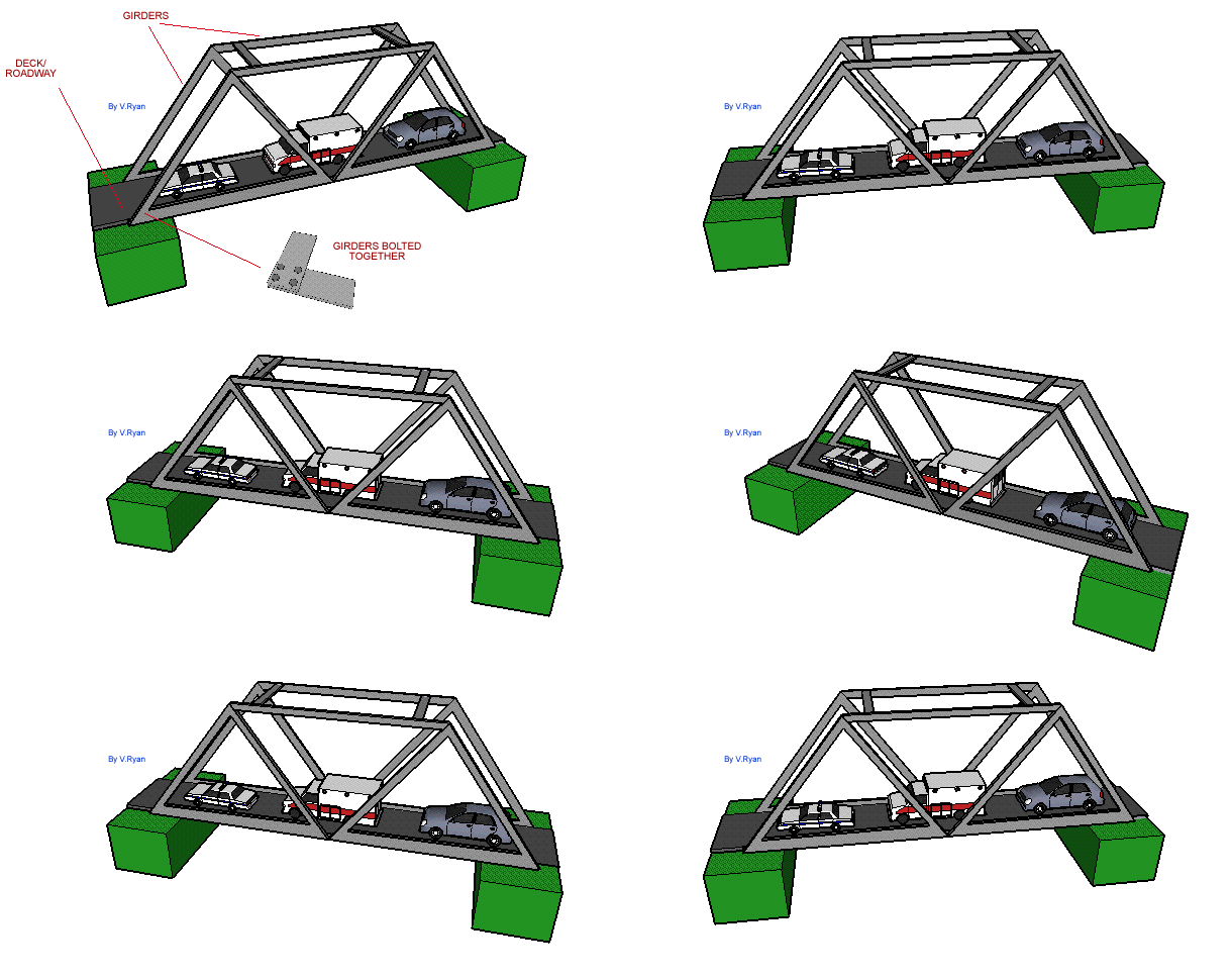
Breaking down essential parts of a bridge structure term guide nov. The two most common types of modern steel girder bridge are plate and box. Bridge girder diagrams. 2411 types of steel girder structures.
It provides advice for those already acquainted with the design of composite i beam bridges on the particular aspects of box girders bridge design and the use of bs 5400. Highway bridges composite box girders. A girder bridge is a bridge that uses girders as the means of supporting its deck. Although normally the box girder bridge is a form of beam bridge box girders may also be used on cable stayed bridges and other forms.
A hollow box balanced cantilever girder bridge with 75 m. A box girder bridge is one in which the principal structural element is one or more closed cells acting in bending. 115 is to be designed for single lane of irc class 70 r or 2. Design of balanced cantilever bridges with diagram.
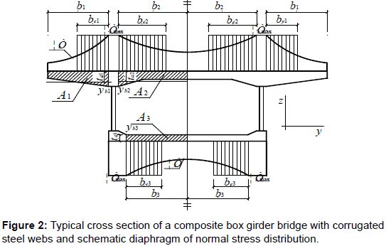
Box girder bridges are commonly used for highway flyovers and for modern elevated structures of light rail transport. The member forces and stresses of each element constituting the bridge girders are produced in the form of a graph. The guide has been reviewed by an advisory group of experienced bridge designers. The stresses due to axial forces and bending moments may be combined and compared with the allowable stresses.
From the main menu select results bridge girder diagrams.

