Buffer Tank Wiring Diagram Hs
In the following article heatspring instructor john siegenthaler discusses 2 pipe verses 4 pipe buffer tank configurations.
Buffer tank wiring diagram hs. This technical instruction document provides the instructions necessary for the installation and maintenance of the aerco buffer tanks in aerco and non aerco systems. The buffer tank is a container in which the cooled medium can be stored. Hss 12 hss 20 hss 30 hss 40 hss 60 hss 80 1 14 1 12 or 2 inlet 34 or 1 ball valve outlets water temperature not to exceed 150 degree max designed for 6 to 10 gallons per ton of buffer volume 115v pump on hydronic heat side 230v pump with water side. Aw wiring diagram 008.
A one tank system vs. The system can be the secondary side of a traditional compressor driven system or a free cooling system where perhaps cooling only occurs at night. Product line sizemb. Aw ladder wiring diagram 009.
Chilled water buffer tank. Minimum circuit ampacities and other unit electrical data are on the unit nameplate. Even state of the art modcon boilers with 51 81 or even 101 ratios between their maximum firing rate and minimum stable firing rate cant always match the heating load imposed by a single small zone such as a towel warmer radiator in the master bathroom on a mild day. I was thinking of placing the buffer tank tees next to each other just beyond where the main boiler pipe comes out of the boiler.
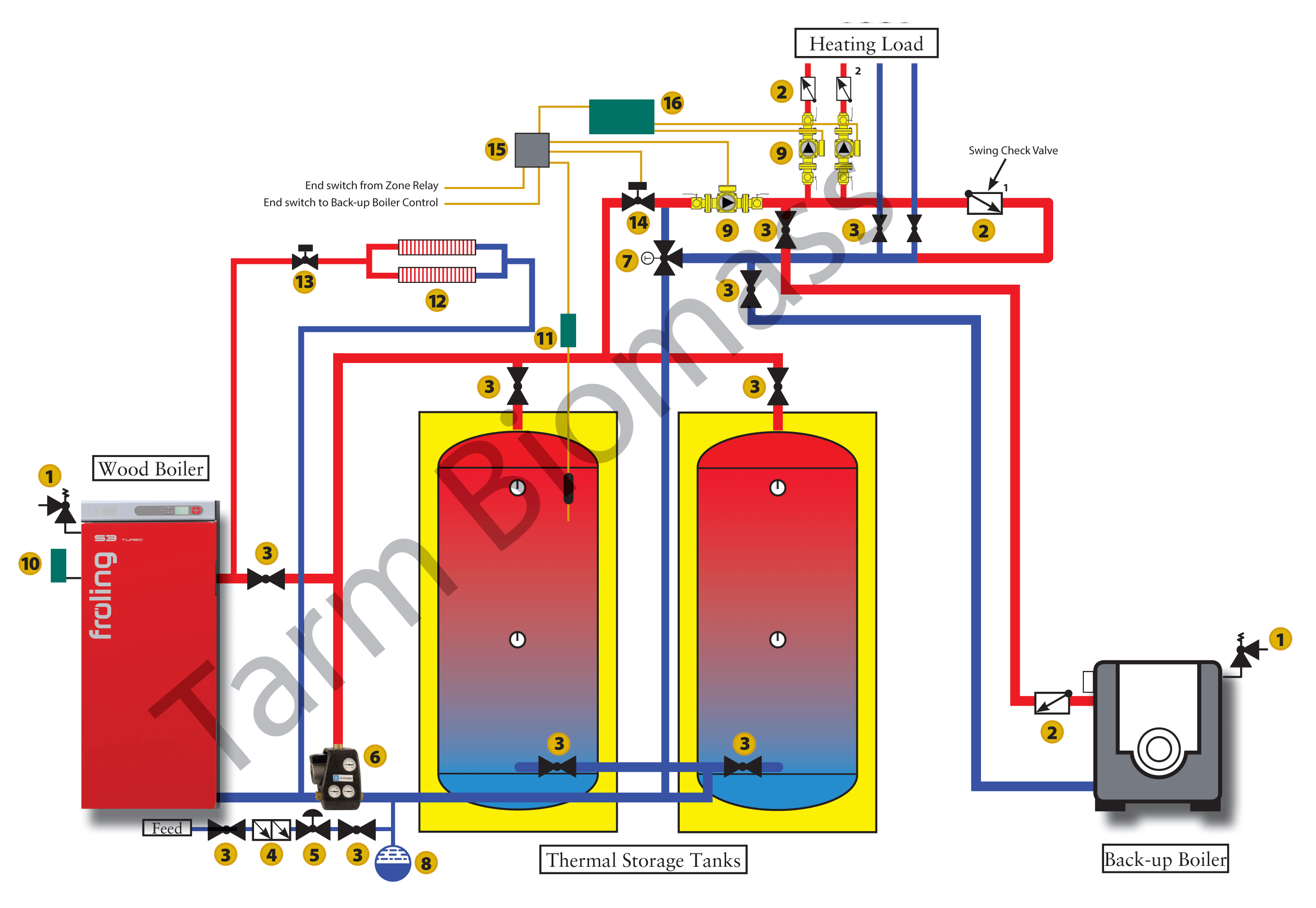
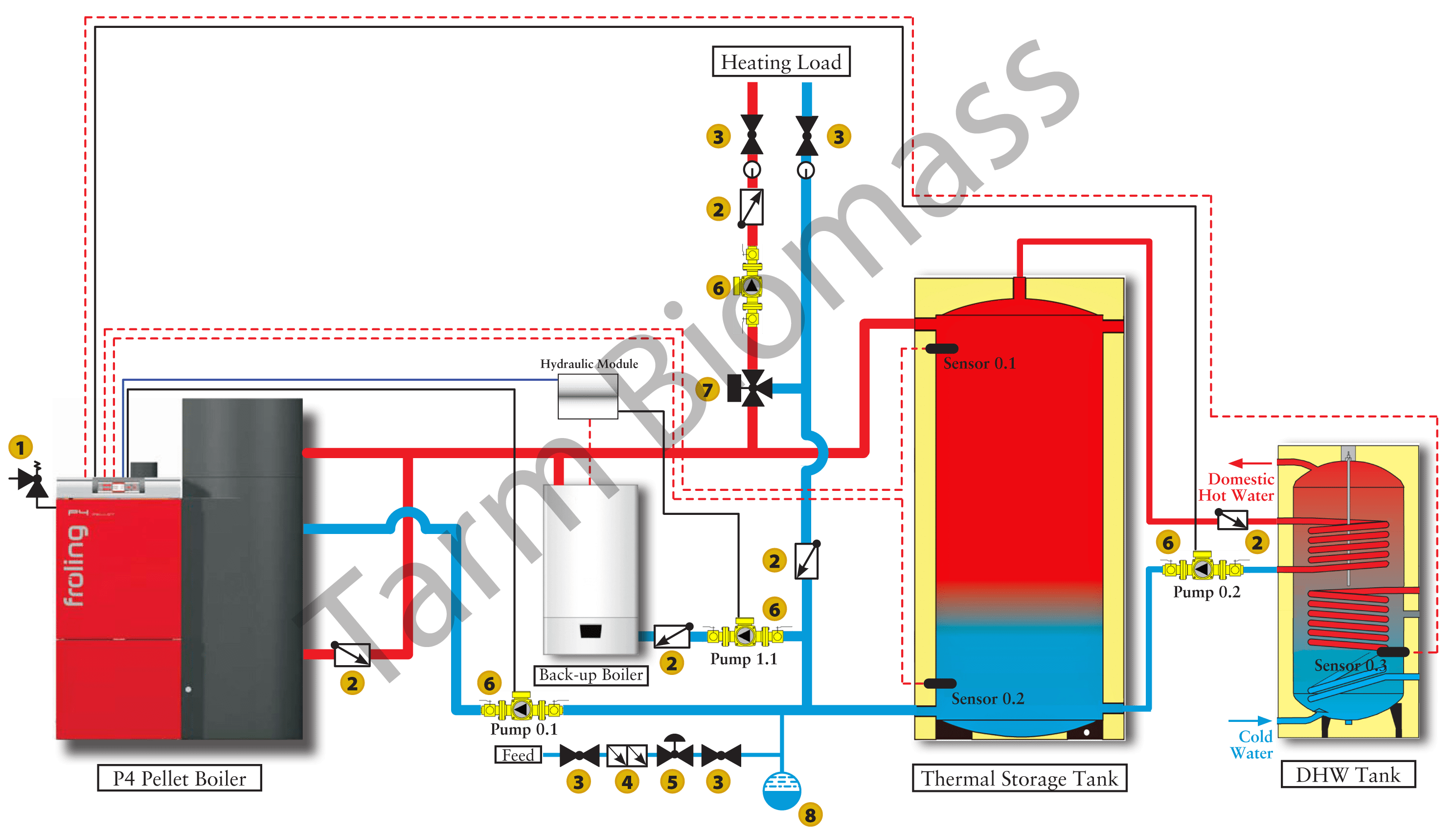
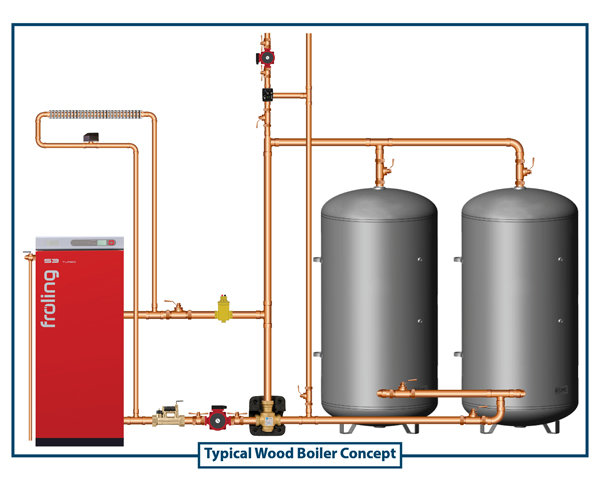
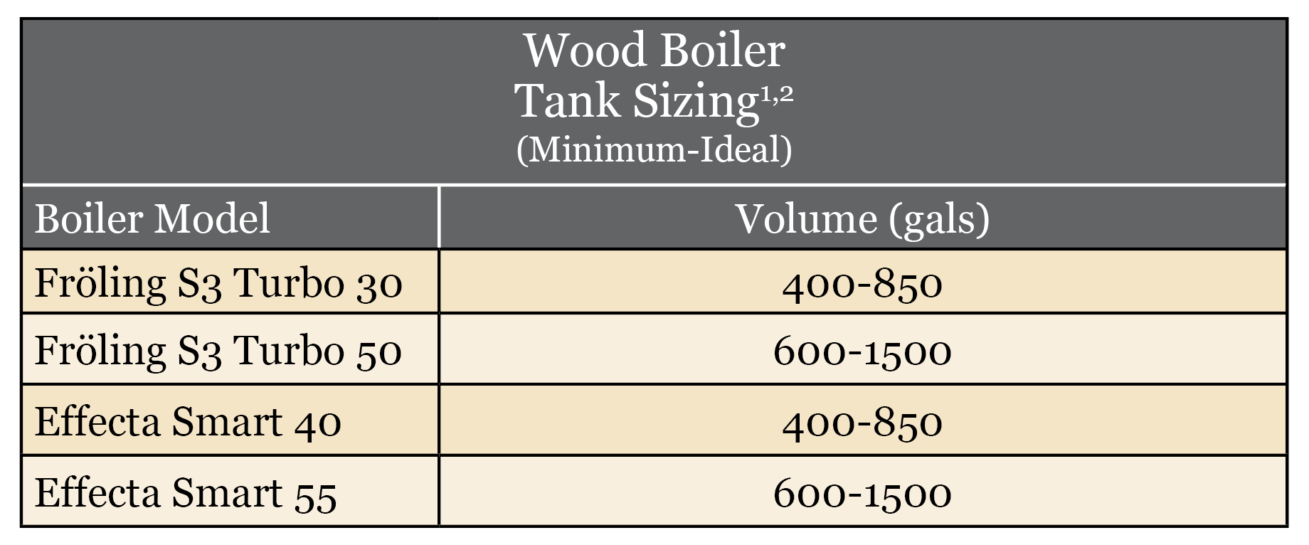
Home products product documentation. Read on to learn more about the importance of a properly sized buffer tank for both wood gasification boilers and boilers fueled by pelletswood chips. Chilled water buffer tank. A larger buffer preheat tank has less chance for btus to be dumped in to the water.
Piping buffer tank i would like to add a buffer tank to my system. Discussion in general discussions started by eisensms. Aerco buffer tank installation and maintenance applies to. Copper fin atmospheric boiler.
Tanks are pretty well insulated. Typical field wiring diagrams are included at the end of the manual. Lochinvar buffer tanks are a cost effective way to enhance your projects bottom line. Your wiring diagram should show the connection scheme.
Squire stainless steel buffer tank. Sizes 20 and 26 ton pump package buffer tank partial heat recovery control panel 847 in 2151 mm pump package buffer tank wire connection compressor pump package 208 in 529 mm. Any applicable water heaterboiler piping system arrangement. Squire stainless steel buffer tank.
A non pressurized stainless steel buffer tank for hydronic heat. Would it be ok to put the supply and return of the buffer tank in the boiler loop on the output side of the boiler. Stainless steel buffer tank. Desuperheater wiring activation question.
Revit product drawings.



_b.jpg)


