Capacitor Start Capacitor Run Motor Circuit Diagram
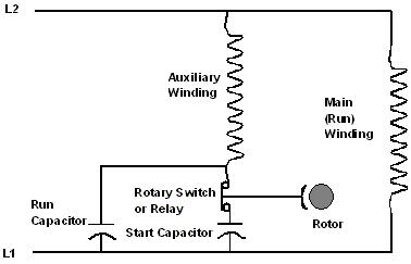
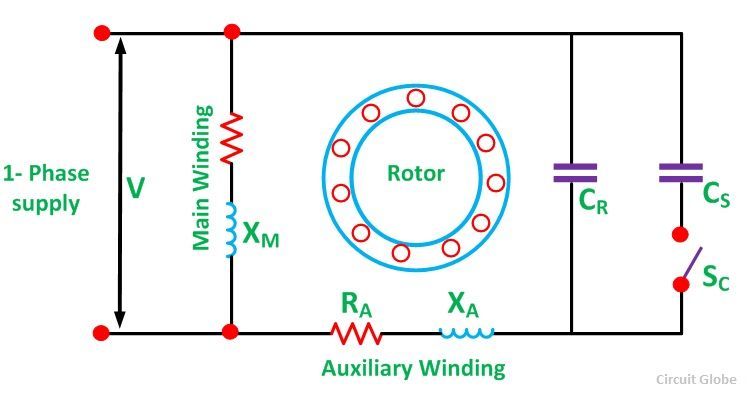
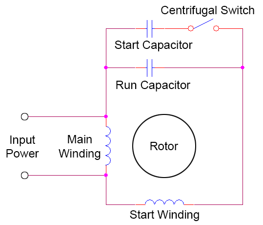
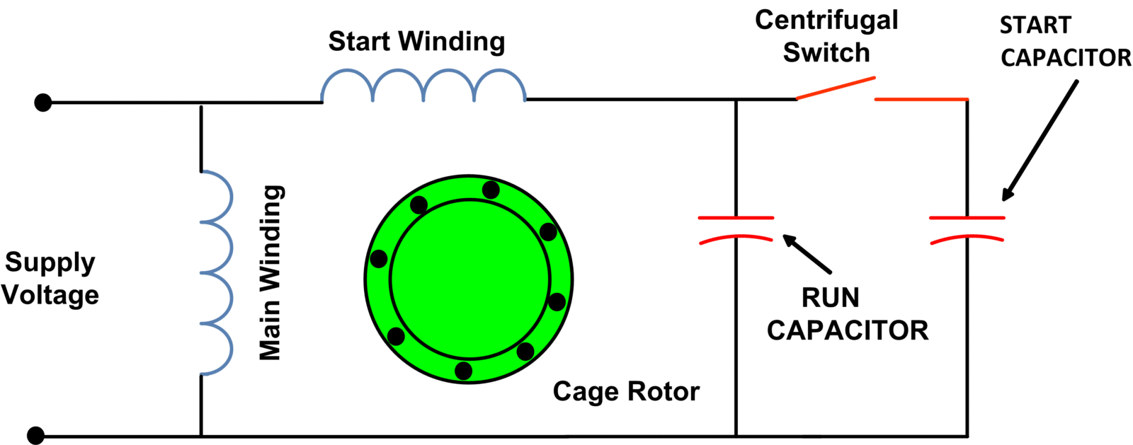
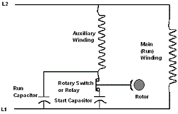
As you can see this circuit has run capacitor and start capacitor.
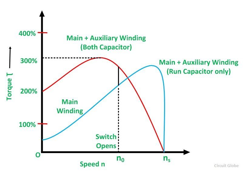
Capacitor start capacitor run motor circuit diagram. In construction these two windings are placed 900 apart in space. Click here to view a capacitor start motor circuit diagram for starting a single phase motor. The name capacitor starts itself shows that the motor uses a capacitor for the purpose of the starting. Also read about the speed torque characteristics of these motors along with its different types.
The figure below shows the phasor diagram of the capacitor start capacitor run motor. The capacitor c r is connected permanently in the circuit and thus it is known as run capacitor. Learn how a capacitor start induction run motor is capable of producing twice as much torque of a split phase motor. The stator has two windings ie.
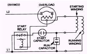
The applications that uses this motor is air compressors high pressure water pumps wood working machinery vacuum pumps and other application that need high torque 1 to 1o hp. A capacitor start capacitor run induction motor is a single phase motor consists of a stator and a single cage rotor. Here is the typical circuit of capacitor runstart induction motor. The run capacitor is long time rated and is made of oil filled paper.
The auxiliary winding is also known as starting winding. Home types of single phase induction motors single phase induction motor wiring diagram capacitor start capacitor run motor circuit wiring diagram and torque speed curve capacitor start capacitor run motor circuit wiring diagram and torque speed curve.
