Crown Block Diagram

You can also order manuals using the manual and safety label lookup tool.
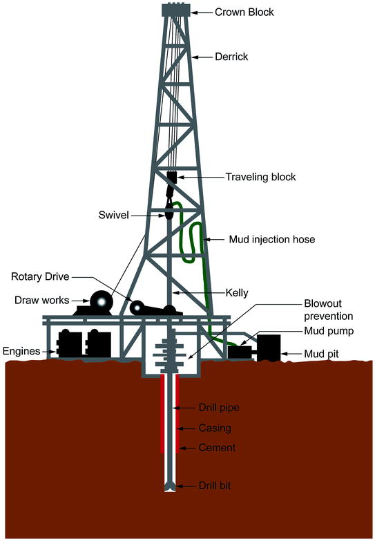
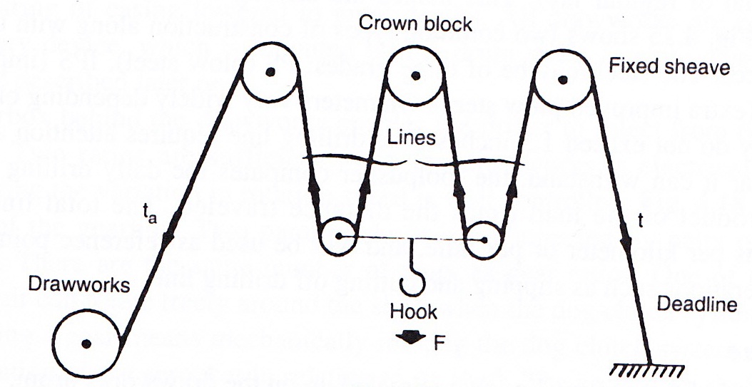
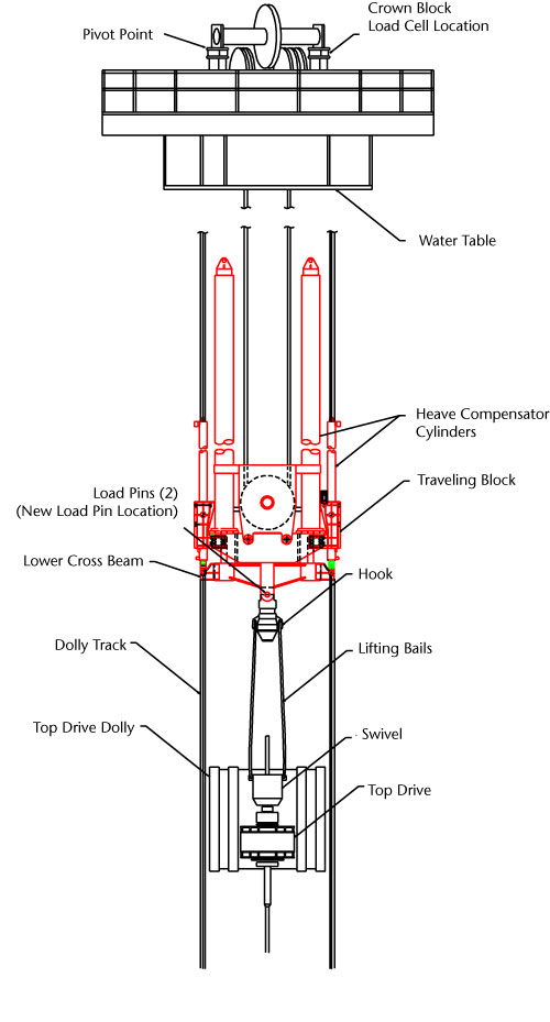
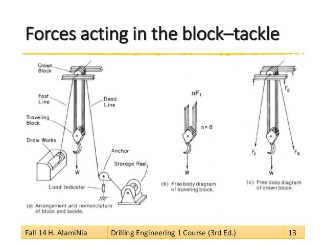
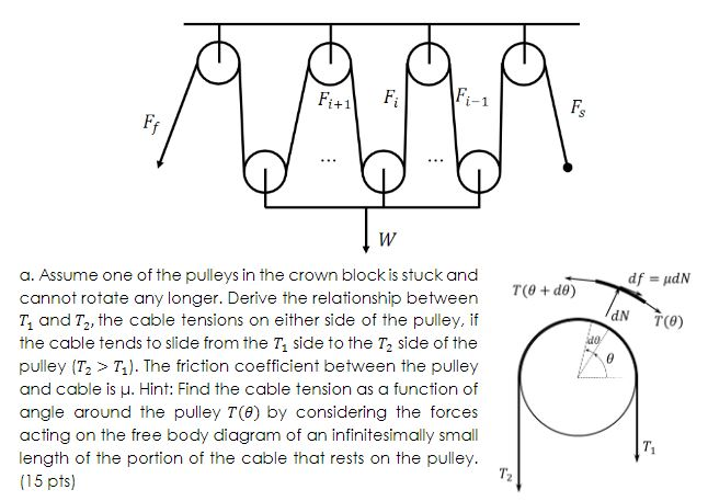
Crown block diagram. It is typically mounted on top of the mud tanks. Working safely is at the top of your list so if your operator manual is lost or missing click on the lift truck model to view its current manual. Page 12 balanced inputs figure 3. Crown block a crown block is the stationary section of a block and tackle that contains a set of pulleys or sheaves through which the drill line wire rope is threaded or reeved and is opposite and above the traveling block.
A tackle block is one element of a system used to lift or drag a load. Using diagram iv as a guide assemble rows. Fuse panel layout diagram parts. There are other elements in the system including the prime mover hoist winch hand support ing structure power available etc.
Using diagram iii as a guide assemble crown units. Amplifier 51 tda2822 51 amplifier reviews 51 amplifier price 51. Typical crown amplifier basic block diagram one channel shown theory voltage translator error output. Layer background and print template b triangles right sides together.
Typical crown amplifier basic block diagram one channel shown micro tech 1200 amplifier service manual theory voltage translator error output device emulation protection voltage translator inverting bridge balance positive lva high side output npn stage high side. Press seam allowance toward print fabric. Crown xls 802 schematic diagram 51 amplifier circuit diagram. Test procedures power base 1 460csl amplifier service manual general information the following test procedures are to be used to verify operation of this amplifier.
Sew pieces together diagram ii. Derrick 14 is the support structure for the equipment used to lower and raise the drill string into and out of the wellbore. When selecting a block for the system in your specific applica. Crown block 13 is the stationary end of the block and tackle.
All of these elements can influence the type of tackle block required. Sew rows together to make cross and crown block. This consists of the sub structure structure below the drill floor level and the mast. Wiring manuals of crown xls 802 manual in jpg files format and the common topics such as xls diagram manual 802 service manuals crown xls owner manuals.
Starer relay headlamp daytime running lamps pcm power relay gas vehicle module air suspension compressor relay starter relay radio amplifier sub woofer amplifier battery charging relay police power relay horn relay lighting control module day time running lamp power door lock power seas fuel filer door release cooling fan relay rear window defrost relay anti lock brake module electric brake controller trailer turn circuit breaker. Degasser not pictured is a device that separates air andor gas from the drilling fluid.

