Crystal Transmitter Circuit Diagram
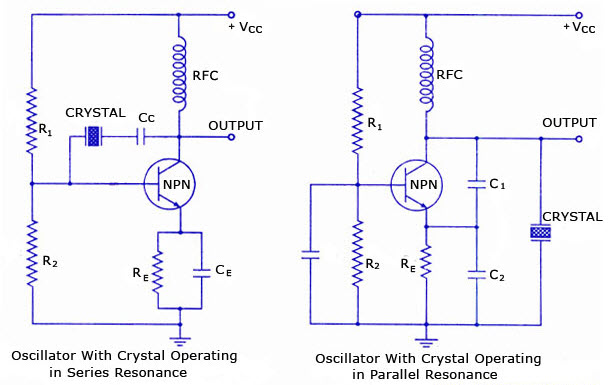
Overview Of Crystal Oscillator Circuit Working With Applications
Overview Of Crystal Oscillator Circuit Working With Applications

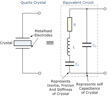
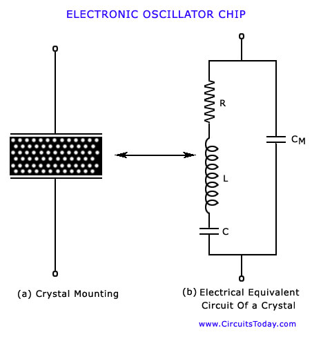
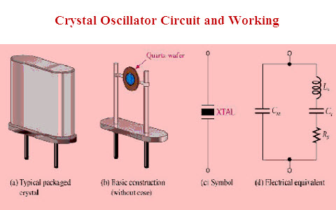
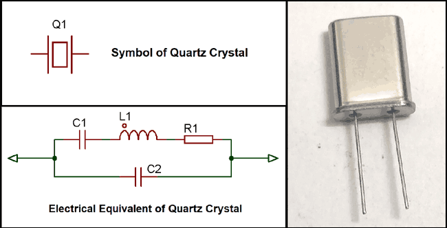
Quartz Crystal Oscillator And Quartz Crystals

The crystal marked jt in the transmitter schematic is a 49860mhz overtone type crystal.
Crystal transmitter circuit diagram. At the first the audio signal is collected using microphone or audio jack. Am transmitter circuit diagram working of am transmitter circuit. Transistor q6 is the final output transistor which can be c2581 or c2053. The heart of the circuit is the electron coupled crystal oscillator shown above.
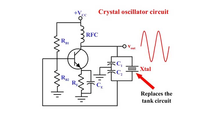
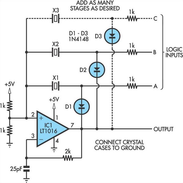
Getting audio input and amplification. At the heart of the circuit is a crystal oscillatora 10mhz crystal is used to generate highly stable carrier frequency. Crystal oscillator circuit diagram the above figure is a 20psc new 16mhz quartz crystal oscillator and it is one kind of crystal oscillators that works with 16mhz frequency. This circuit combines the functions of oscillator and amplifier.
Here is the circuit of a medium power am transmitter that delivers 100 150 mw of radio frequency rf power. The aa8vw8exi 6cl6 one tube transmitter by greg latta aa8v schematic diagrams and circuit descriptions. The working of this am transmitter is divided into 3 stages. Am transmitter circuit crystal am transmitter circuit oscillator coil.
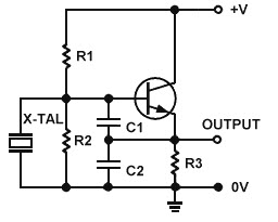
The aa8vw9exi 6cl6 one tube transmitter schematic diagrams and circuit descriptions. One of the most common circuits used for crystal oscillators is the colpitts configuration as shown below.

Quartz Crystal Oscillator And Quartz Crystals
Overview Of Crystal Oscillator Circuit Working With Applications
Transistor Crystal Oscillator Circuit Electronics Radio
Quartz Crystals And Oscillators Part 1 Crystal Basics

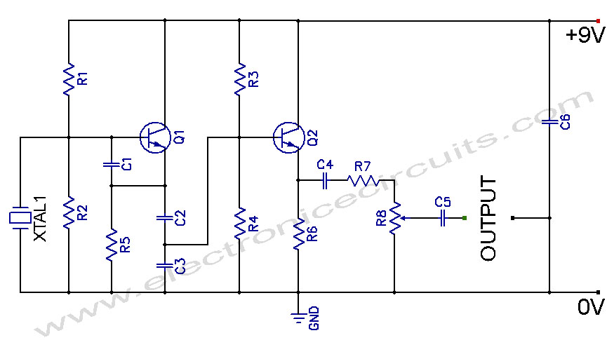
Diy Crystal Oscillator Circuit

Quartz Crystal Oscillator And Quartz Crystals
Crystal Oscillator Electronic Circuits And Diagrams
Crystal Controlled Oscillator Circuit Electronic Circuits

Colpitts 1mhz To 20 Mhz Crystal Oscillator Circuit Circuit

Accurate 1 Khz Square Wave Crystal Oscillator Circuit

Quartz Crystal Oscillator And Quartz Crystals
Overview Of Crystal Oscillator Circuit Working With Applications

Crystal Oscillator Circuit Is Ultralow Power Edn

The Johnson Viking Ranger Crystal Oscillator Schematic

Crystal Am Transmitter Detailed Circuit Diagram Available
Crystal Oscillator Circuit Page 3 Oscillator Circuits

Crystal Oscillator Circuit Addendum
Quartz Crystal Oscillator
