Defrost Timer Wiring Diagram For F250
Low cost defrost control dr defrost relay coil dft defrost thermostat lps low pressure switch rvs reversing valve solenoid hps high pressure switch in.
Defrost timer wiring diagram for f250. Refrigerator defrost timer wiring diagram sample. The dtav40 may also be used to replace paragon 8040 and precision 6040 series time terminated defrost timers. It shows the components of the circuit as simplified forms and also the power as well as signal connections in between the gadgets. When i cannot find the wiring diagram for a whirlpool manufactured fridge the following has worked for me when installing the whirlpool universal timer the one with the innocuous looking dangling black wire aaccording to the timer manual for whirlpools if your timer connector has a white wire it is continuous or possible a cumulative.
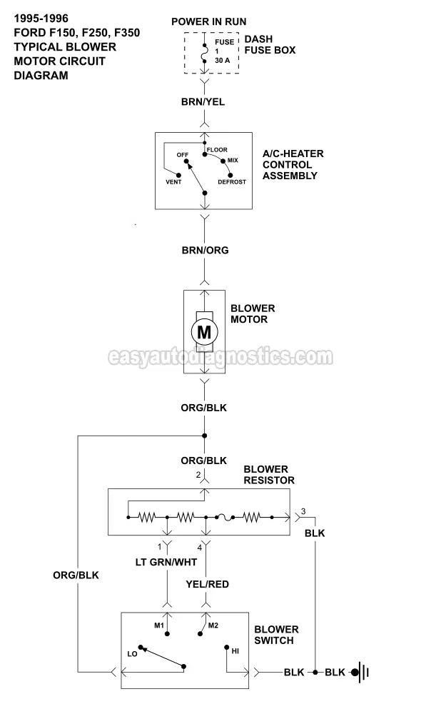
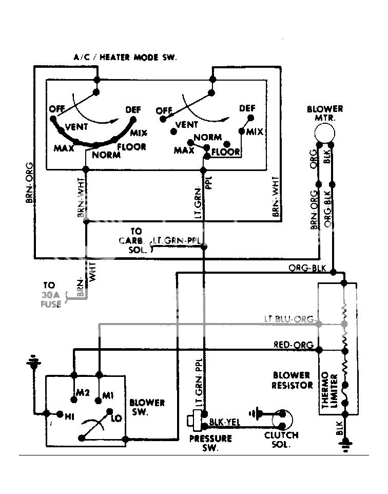
Refrigerator defrost timer wiring diagram sample. A wiring diagram for an f250 ac system can be found in the cars maintenance manual. It shows the elements of the circuit as streamlined forms and also the power and also signal links in between the devices. 50 60 hz power consumption.
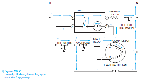
Refrigerator defrost timer wiring diagram image. Variety of walk in freezer defrost timer wiring diagram. Defrost timer circuits schematic diagram sample and definition many of the refrigeration appliances used in the home are frost free the frost free appliance could more accurately be termed automatic defrost. Defrost timer 8000 series defrost duration solid copper contacts line voltage 120208 240v ac 40 amp 2 hp pins indicate defrost start time.
Frugalpreppers garage garden 1545473 views. Walk in freezer paragon defrost control. The dtav40 defrost timer is equivalent in function terminal identification with appropriate terminal block label attached and wiring to the paragon 8140 and precision 6140 series defrost timers. A wiring diagram is a streamlined standard pictorial depiction of an electrical circuit.
A wiring diagram is a streamlined standard pictorial representation of an electrical circuit. 18 30 vac frequency. Should ac compressor stay on when heater control moved to defrost in a 2000 durango. Defrost timer wiring diagram specifications input voltage.
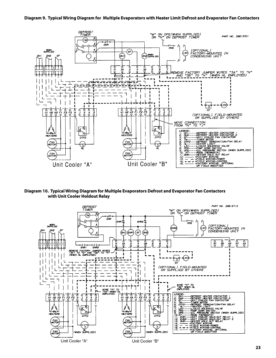
Paragon defrost timer 8145 20 wiring diagram gallery collections of timer wiring diagrams furthermore paragon 8145 20 wiring diagram. 1 watt maximum output o w2. Yes the ac will run in the.


