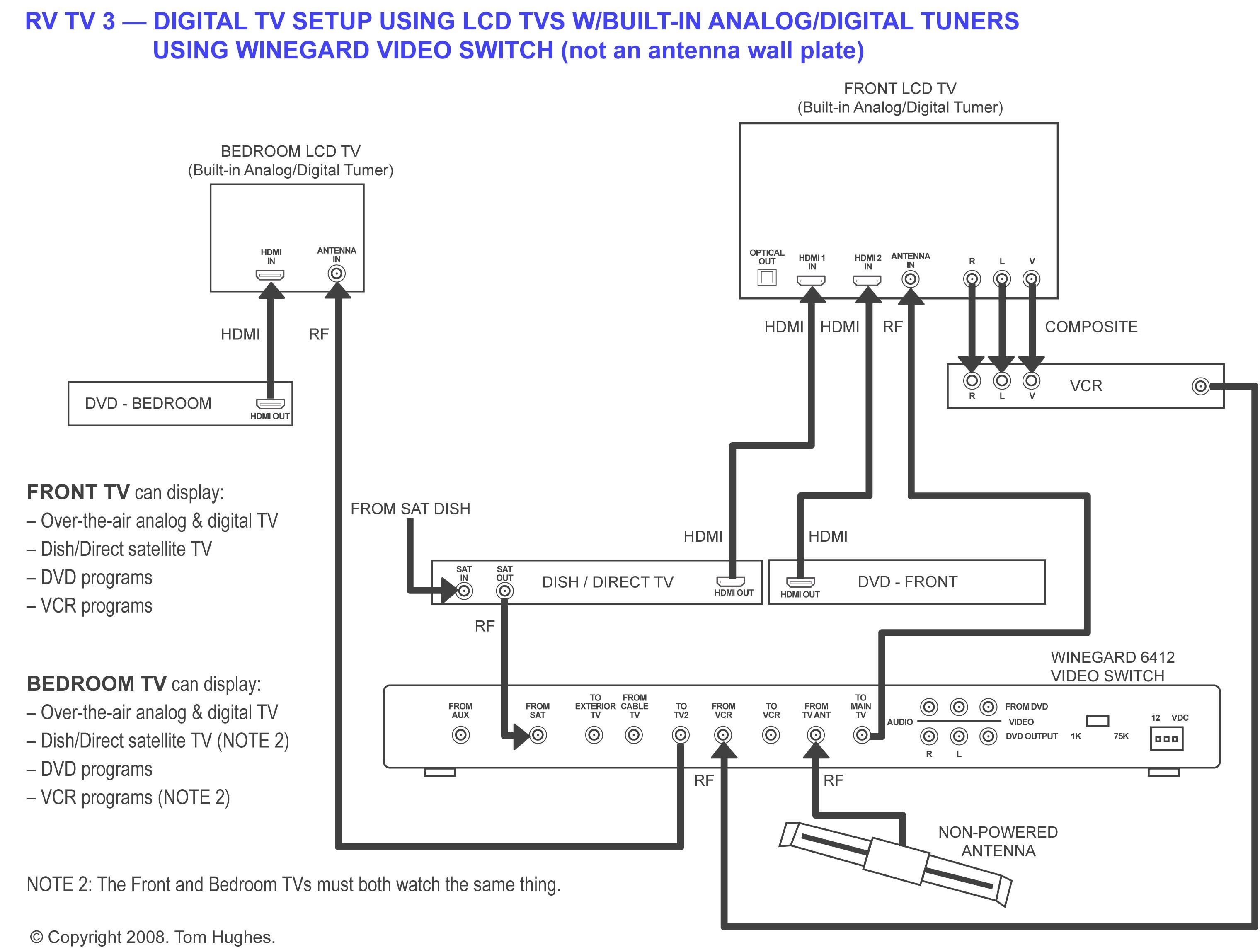
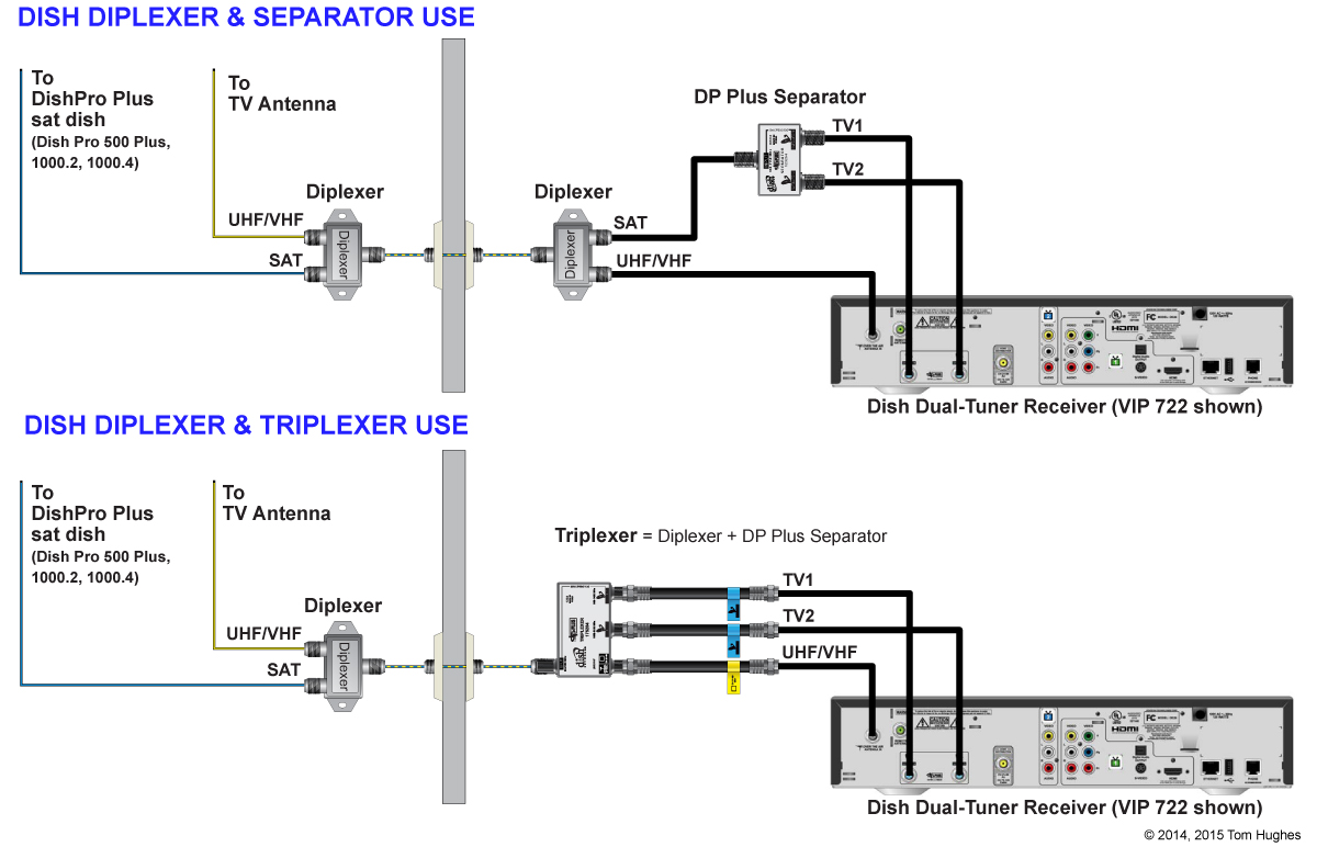
Dish Dp34 722k Wiring Diagram

Page 75 dishpro wiring diagrams lnbf ishes hree ingle utput hree dp34 s ables witch ultiple eceivers this diagram leaves out grounding to be clear.
Dish dp34 722k wiring diagram. Make sure to use drip loops and to ground the system per the national electrical code nec and all local electrical codes. View and download dish network dishpro user manual online. The lnbfs or low noise block feed horns of the antenna are powered by the dish receivers. Installation diagrams diagram 2.
Dish pro plus 44 connections the wiring diagram in this guide omit cable drip loops and grounding for clarity. Dish network vip 722 configuration wiring schema. Wiring diagrams dish 500 with dishpro twin lnbf and a dp34 switch connect both ports connections on the dishpro twin lnbf to any two ports on the dp34 switch that are marked to dish make sure there is no more than 200 feet of cable between the lnbfs and the receivers. It provides 3 satellite orbital feeds via rg 6 coaxial cabling that can be expanded to be able to feed up to 15 dish receivers for 15 tvs.
235 w x 185 h. Ford focus parts diagrams. Make sure there is no more than 200 feet of cable between the lnbf and the receivers. 1100 1190 dish 500 35 diagram 2.
Wiring diagrams figure 6. It can also function as a supercool way to control your receiver. Make sure you ground the system per the national electrical code nec and all local electrical codes. For the unacquainted slingguide is a fully featured web based interface for managing and controlling your dish dvr.
The dish 10002 antenna is the standard residential antenna used today.


