Dmx512 Wiring Diagram
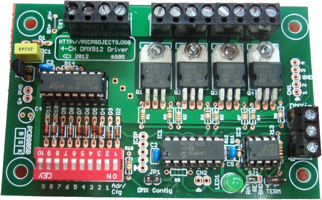
Dmx 512 led controller with led display.
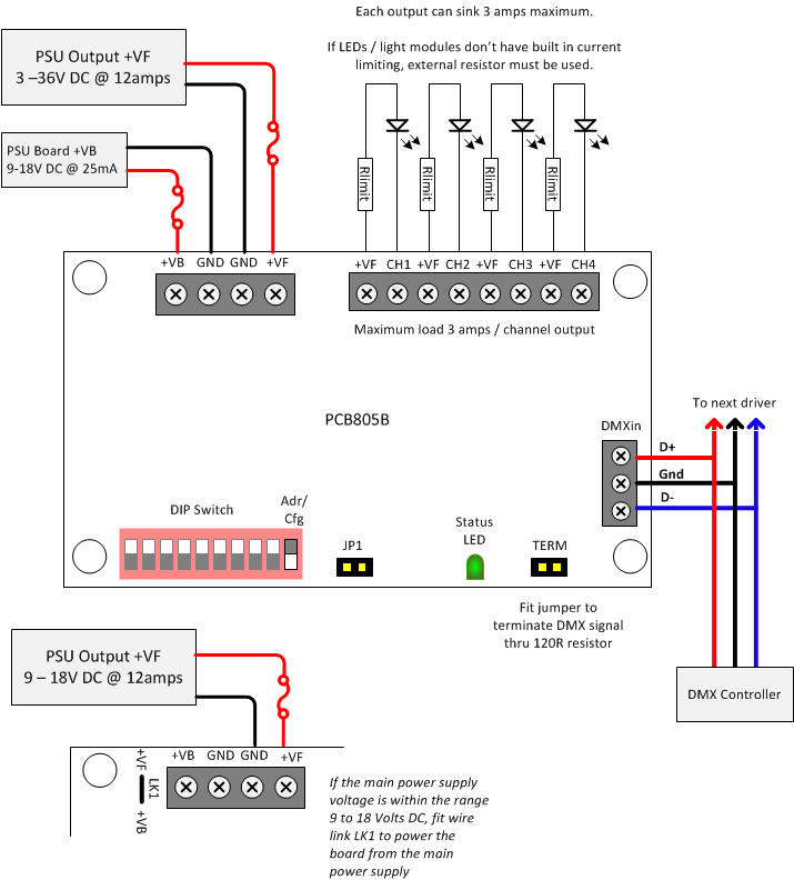
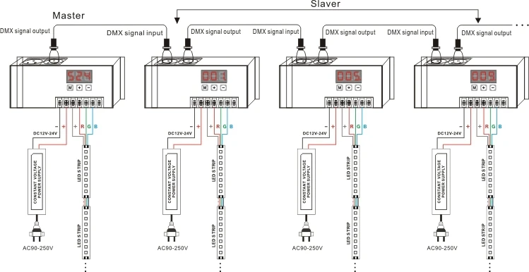
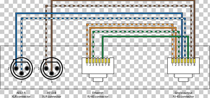
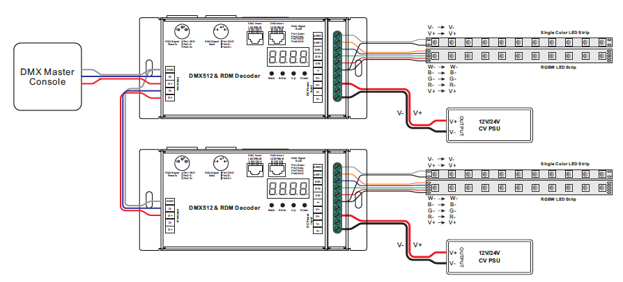
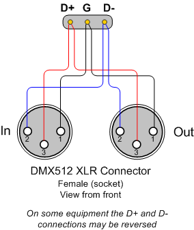
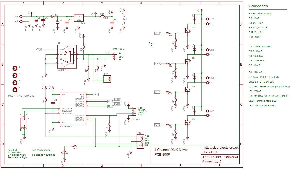
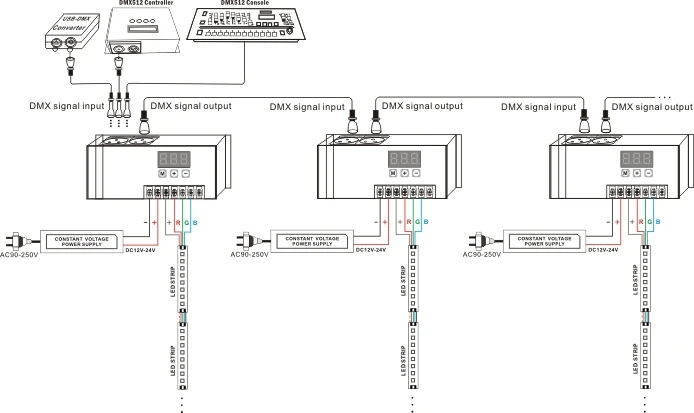
Dmx512 wiring diagram. Pinout of dmx dmx512 and layout of 5 pin xlr male connector and 5 pin xlr female connectordmx digital multiplex is a communications protocol used mainly to control stage lighting. Dmx addressing 512 individual device addresses available per. In this diagram an easy stand alone dmx controller is shown but you can use any console that outputs standard dmx. The dmx512 wiring follows the rs 485 standard similar to qs digital link digital cable is run in a daisy chain to each dmx device each device is addressed to specific dmx channels dmx link wiring grafik eye link wiring.
How to wire dmx lighting systems. The pwm signals control led drivers output boards mosfetresistor based regulation or constant current regulators which are selected based on th. Home support learning center how to wire dmx lighting systems. Lets say you have 4 led fixtures.
All wiring must be in a continuous run and daisy chained. How to wire dmx for stage lighting. It is a form of the rs 485 architecture. Network wiring consists of a shielded twisted pair with a characteristic impedance of 120 ohms with a termination resistor at the end of the cable furthest from the controller to absorb signal reflections.
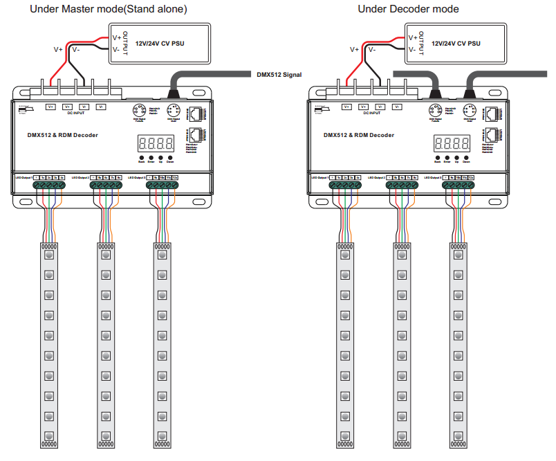
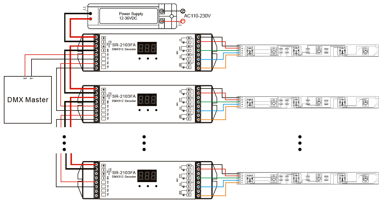
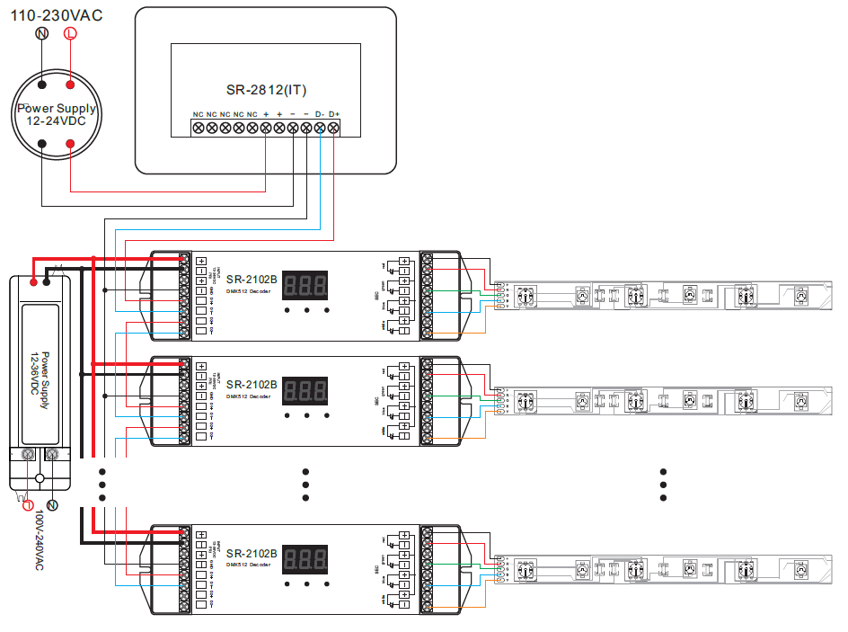
Wiring instructions below is a circuit diagram that illustrates how to wire the dmx512 pixelpro decoder to pixelpro lights a power supply and a dmx controller. The dmx512 standard states that a maximum of 32 unit loads can be. A quick guide to what you really need to know about dmx512. Learn about best practices for wiring eldoled drivers in a dmx lighting system.
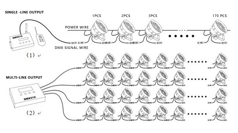
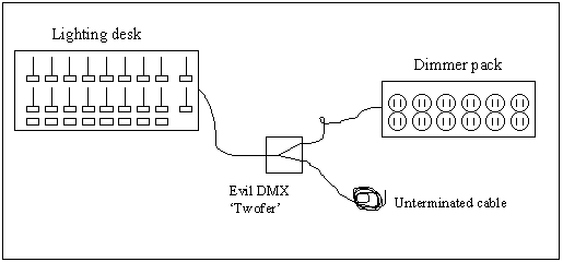
Dmx512 has two twisted pair data paths although specification currently only defines the use of one of the twisted pairs. The daisy chain is a simple wiring method where you wire each fixture looping out of the previous fixture to create a line of fixtures connected back to the console. No tees are permitted. Star wiring is only allowed in conjunction with an opto splitter.
Maximum cable length is 1800 ft when used for dmx only. Cable shield may be grounded at one end only preferably at the control console. Most fixtures will have a dmx input and a dmx output. A compact easy to assemble led controller outputs ttl pwm signals for red green and blue leds.
Learn about best practices for wiring eldoled drivers in a dmx lighting system. In this diagram the easy stand alone dmx controller is used to control the pixelcontrol led lights but you can use any console that outputs standard dmx. Keep signal lines away from.
