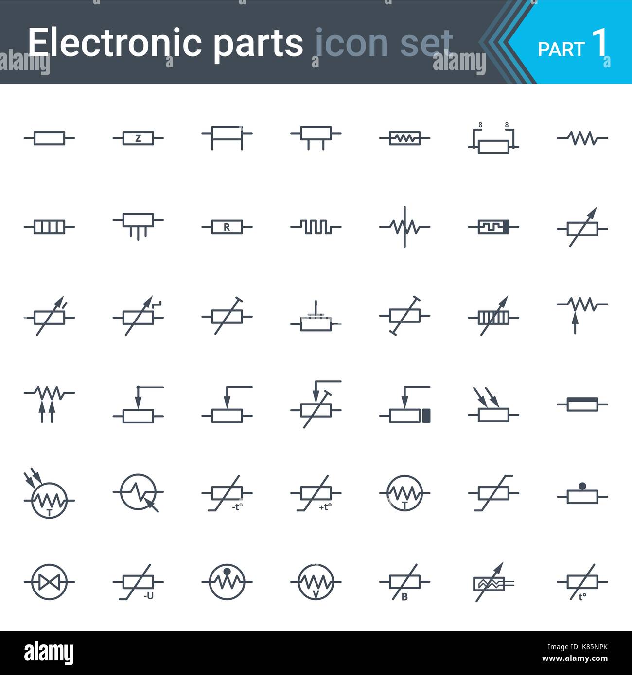
Electronic Circuit Diagram Symbols

It is also known as ground.
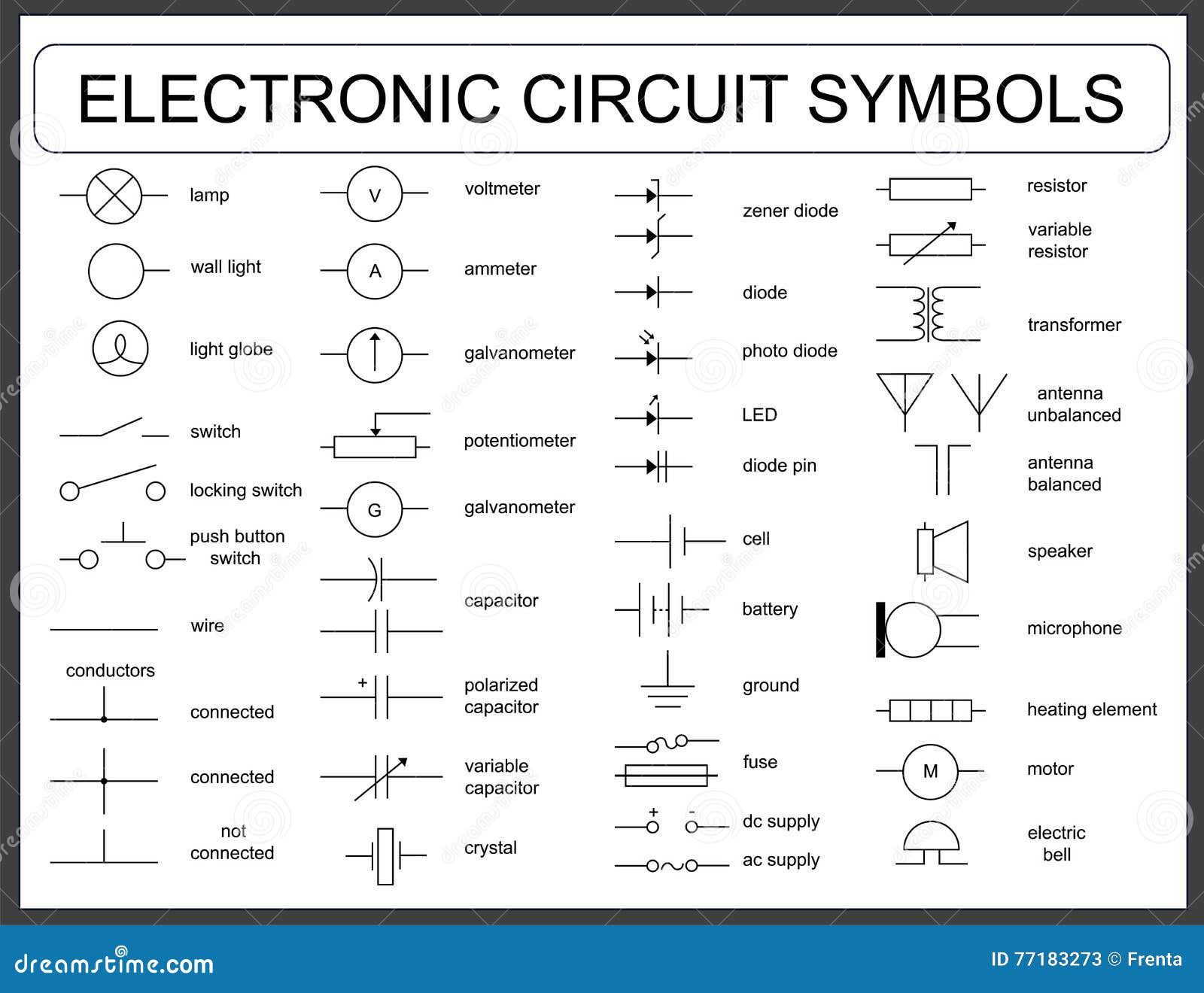
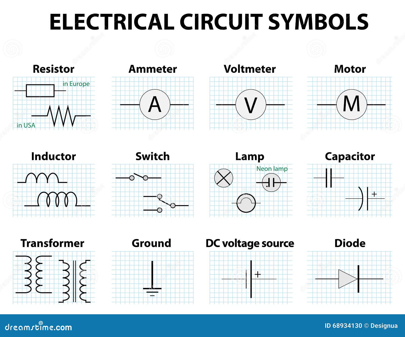
Electronic circuit diagram symbols. Push to break switch this type of push switch is normally closed on it is open off only when the button is pressed. The symbols are very important to represent electronic components in a circuit diagram without electronic symbol the design of circuit and schematics are very difficult and also knowing the components is very must to read the circuit diagram representation. For some electronic circuits this symbol is used for the 0v zero volts of the power supply but for mains electricity and some radio circuits it really means the earth. Electronic circuit symbols in electronic circuits there are many electronic symbols that are used to represent or identify a basic electronic or electrical device.
This is the switch used to operate a doorbell. It is a type of transducer which converts electrical energy or electric current to light. The zener diode abbreviated as zd is a special diode. There are many electrical and electronic schematic symbols are used to signify basic electronic or electrical device.
This article gives some of the frequently used symbols for drawing the circuits. Electronic component circuit symbols electronic circuits are key to designing and defining electronic circuits. Push switch push to make a push switch allows current to flow only when the button is pressed. Switches component circuit symbol function of component.
The led is more efficient than many other light sources. Table of electrical symbols. Electrical symbols electronic symbols in pdf the largest collection of symbols in the network in pdf formatfor consultation and interpretation of components devices and electrical and electronic circuit. Even more the electronic components have terminals and each will have its own name and polarities.
They are mostly used to draw a circuit diagram and are standardized internationally by the ieee standard ieee std 315 and the british standard bs 3939. Or gate outputs 1 when any input is 1. Nor gate outputs 0 when any input is 1. These are mostly we used for draw circuit diagrams.
Earth ground a connection to earth. Each different type of component has its own circuit symbol enabling circuits to be drawn and read concisely. Multiplexer mux 2 to 1 connects the output to selected input line. Nand gate outputs 0 when both inputs are 1.
Electrical symbols or electronic circuits are virtually represented by circuit diagrams. Xor gate outputs 1 when inputs are different. The basic is passive and active components r c l resistor capacitor inductor are passive and most of the semiconductors. And gate outputs 1 when both inputs are 1.


