Flygt Submersible Pump Wiring Diagram

Flygt Wiring Diagram Diagram Schematic

Flygt Wiring Diagrams Wiring Diagram
Flygt Submersible Pump Wiring Diagram Wiring Schematic Diagram

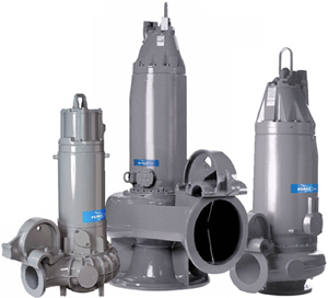
Submersible pumps basic information and diagram.
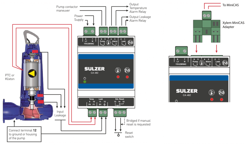
Flygt submersible pump wiring diagram. If not the structure will not work as it should be. Flygt 3153 installation operation and maintenance manual. Single phase submersible pump control box wiring diagram 3 wire submersible pump wiring diagram in submersible pump control box we use a capacitor a resit able thermal overload and dpst switch double pole single throw. Each part should be placed and linked to other parts in particular way.
Page 10 introduction and safety spare parts xylem guarantees that spare parts will be available for 15 years after the manufacture of this product has been discontinued. Submersible pump starter increase in rapidly use in city because water lifting. Here is the complete guide step by step. 3 wire submersible well pump wiring diagram 3 wire submersible well pump wiring diagram every electric structure is made up of various diverse pieces.
A submersible pump consists of a centrifugal pump driven by an electric motor. In which i control a three phase submersible pump motor using magnetic contactor. The wiring connection of submersible pump control box is very simple. Submersible pump starter use for starting of induction motor that connected with pump for lifting water from deep.
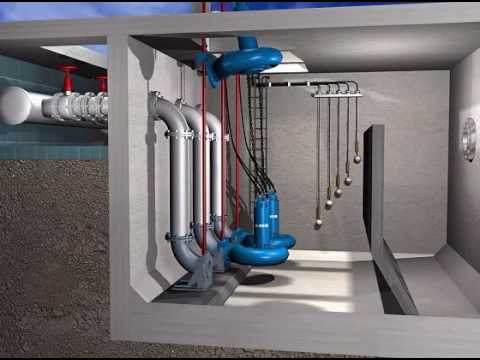
Submersible pumps basic information and diagram parts of submersible pump. The pump and the motor are contained in one housing submersed below the permanent water level within the well casing.

Wire Diagram Flygt Pump Wiring Diagram

Flygt Submersible Pump Wiring Diagram Wiring Schematic Diagram

Flygt Wiring Diagram Wiring Schematic Diagram

Flygt Pumps Manuals

Flygt Pump Wiring Diagrams Catalogue Of Schemas

Wrg 2199 Kobelco Sk03 Wiring Diagram

Submersible Pumps Submersible Pumps Wiring Diagram

Flygt Wiring Diagram Wiring Diagram

M 3085 Xylem Us
Submersible Pump Installation

Wrg 4272 Flygt Submersible Pump Wiring Diagram

Flygt Ready 8 Submersible Drainage Pump

Flygt N Technology Pump N 3171 Xylem Us Xylem Indonesia

Septic Pump Wiring Diagram 1 Wiring Diagram Source

Flygt S Innovative Service Cart For Horizontal Dry Pit

Flygt Ready Submersible Pump Parts Spares Maris Pumps
Flygt A Xylem Brand Submersible Mixer Sewage Pump

Flygt Nx 3069 Sewage Pump
