Franklin Electric Motor Wiring Diagram

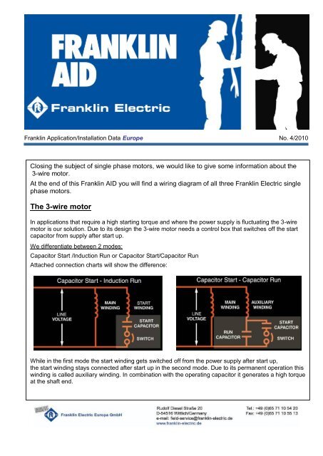
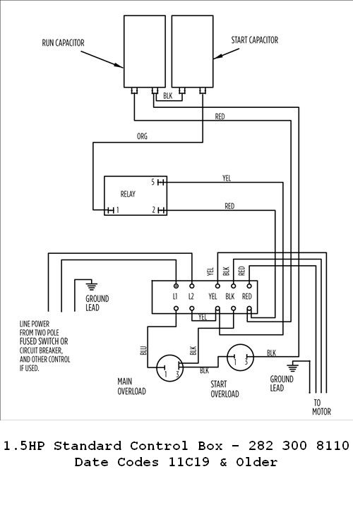
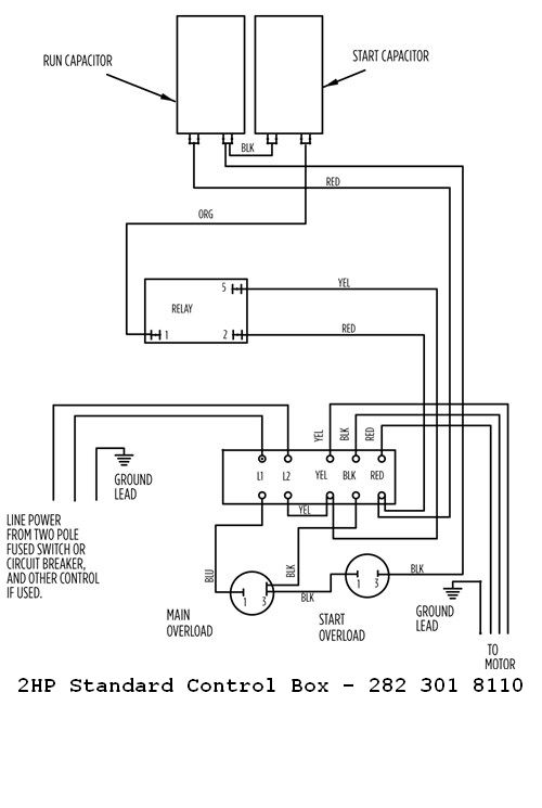
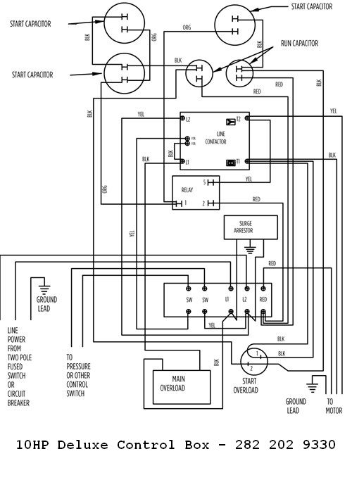
A three wire single phase pump requires a motor control box incorporating overload relays.
Franklin electric motor wiring diagram. Franklin electric co inc. Control box wiring diagrams. Franklin electric motor wiring diagram the submersible motor is a reliable efficient and trouble free means of powering a pump. Franklin single phase controls are designed and optimized specifically for franklin electric motors.
Its needs for a long operational life control box wiring diagrams. Controls are an integral part of a submersible motor power system. 1 shows a typical wiring diagram for a two wire installation. Franklin electric control box wiring diagram welcome in order to our weblog on this time im going to show you in relation to franklin electric control box wiring diagramand today this can be the very first image.
Our website uses cookies for analytics and to enable dynamic contentlearn more. Warning serious or fatal electrical shock may result from failure to connect the motor control enclosures metal plumbing and all other metal near the motor or cable to the power supply ground terminal using wire no smaller than motor cable wires. Our website uses cookies for analytics and to enable dynamic contentlearn more. And directly from franklin electric.
Control box wiring diagrams continued cookies. Rigorous component testing ensures the most robust products in the industry. Our website uses cookies for analytics and to enable dynamic contentlearn more.


