Ge Motor Control Wiring Diagram

If you are in need of a replacement wiring diagram you can determine where to find it on your appliance by visiting.
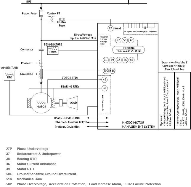
Ge motor control wiring diagram. Does anyone know of a website or place to call or mail to find out. The motor control center. Wiring diagrams show the connections to the controller. Connection diagram drawings outline and dimensional publication type 1995 csi master format 2004 csi master format application and technical brochures catalogs and buyers guides connection diagram drawings outline and dimensional installation and instruction software specifications guideform.
I bought an old air compressor that has a 15hp electric motor made by ge. Wiring diagrams sometimes called main or construction diagrams show the actual connection points for the wires to the components and terminals of the controller. Improper wiring can kill injure start fires burn out motors or anyall of the above. How to obtain a wiring diagram or schematic.
A wiring diagram mini manual is included with each appliance. Ge motor control centers are constructed of standardized heavy gauge vertical sections housing vertical and horizontal buses wiring channels and compartmented control units. Wiring diagrams found in these guides to. Shipping splits are bolted together to form a single line up assembly.
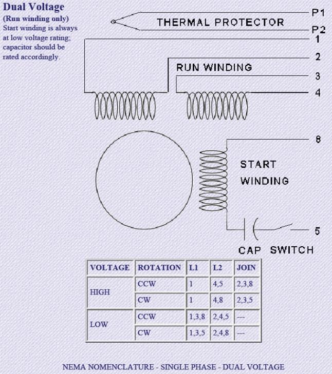
Basic wiring for motor control technical data. 3ph starter3ph motor line voltage control three phase 3ph motor starter controlling a three phase motor rev 08 aug 2006 the above wiring diagram assumes your magnetic starter has a 240v coil. Removing the two bolts from the motor control end bell and disconnecting the 3 pin plug to the motor. Barely readable nameplate may say 5kc184ag201bu googling that model number suggests its a ge and the ag in the model number is probably wrong.
Units are mounted and wired in accordance with the wiring class specified. I got an old motor missing the cover with the wiring diagram.


