Grasslin Time Clock Wiring Diagram

How To Wire Intermatic Et Series Timer

Am Changing My Diehl 880 Timer For A Grasslin Fixya

Need Confirmation On The Wiring Of This Digital Timer

Do not move the clock hands on the timer.
Grasslin time clock wiring diagram. To select mode simply slide the switch as follows. If the coil is frost free the timers can also be terminated by temperature or pressure switches before the programmed defrost termination time has been. User manuals grasslin timer operating guides and service manuals. Figure 4 7 5 type 1 enclosure figure 3 pcb latch interior protective cover ul type.
Page 19 internal wiring diagram qe1 nb carry out wiring installation using appropriate diagram as shown. Proper position from table below and wiring diagrams indicated. Terminate all ground wires to ground lug on bottom of enclosure. Nb when the towerchron qe1 timeswitch is to be used with a combination boiler always refer to the boiler manufacturer instructions concerning wiring before using the information contained in this manual.
Time initiated time terminated grasslin mode selection wiring diag. Time initiated pressure terminated. Moving the clock hands can damage the timer. Grasslin time clock set up instructions youtube jun 26 2013 replacing a grasslin time clock in your saltwater chlorinator.
Time initiated pressure terminated separate pressure switch required see instructions time initiated remote temperature or pressure terminated cross ref. Grasslin time clocks are available from. Download 58 grasslin timer pdf manuals. Wire in accordance with national and local codes see wiring diagrams.
Replacing a grasslin time clock in your saltwater chlorinator. Grasslin time clocks are available from direct pool supplies. Grasslin defrost timer wiring diagram shop for paragon defrost timer wiring diagram. Time initiated time terminated grasslin mode selection wiring diag.
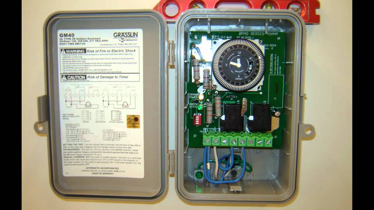
Input voltage shall be 120 208240 or 277vac. Furnish and install a grasslin gm40 multi volt series 24 hour or 7 day time switch with captive trippers and quartz or syn chronous drive. The grasslin dtav40 series auto voltage defrost timer is applicable to air defrost compressor shutdown and electric or hot gas defrost systems where the defrost is terminated by the timer. Price comparison consumer reviews and.
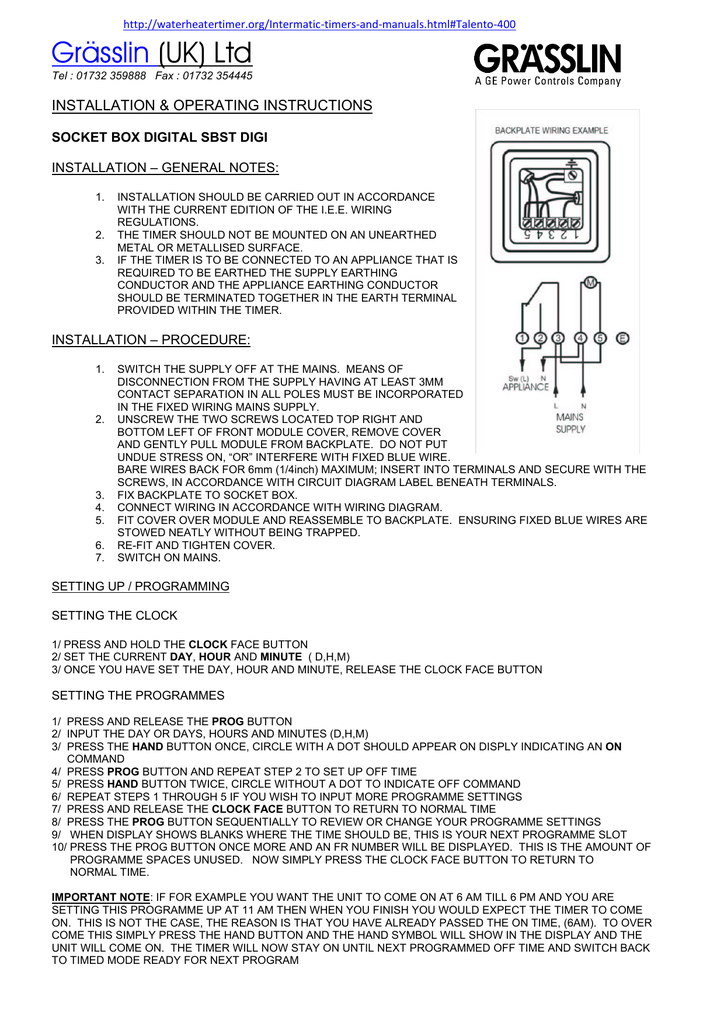
Grasslin Uk Ltd Installation Amp Operating Instructions

Timer Modules

T 49f Wiring Diagram Swapping Timer On True T49f Freezer

Intermatic Defrost Timers And Manuals

Intermatic Defrost Timers And Manuals

How To Wire Gm40 Gm40av Gm40ave Whq Series

How To Wire Gm40 Gm40av Gm40ave Whq Series
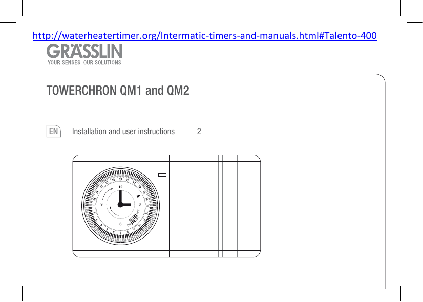
Towerchron Qm1 And Qm2 Installation And User Instructions

Intermatic Timers And Manuals

Fiorentini Adalberta Fallaci Collections Electrical Wiring

Grasslin Defrost Timer Wiring Diagram Refrigerator Defrost
Gm 40 Time Clock

Paragon Timers And Manuals

Woods Timer Wiring Diagram Questions Answers With

Paragon Defrost Timer Wiring Diagram Wiring Library

Defrost Timer Schematic Wiring Diagram

Precision Multiple Controls Official Website Your Source

Intermatic Time Clock Diagram Wiring Diagram Data
