Ignition Module Wiring Diagram

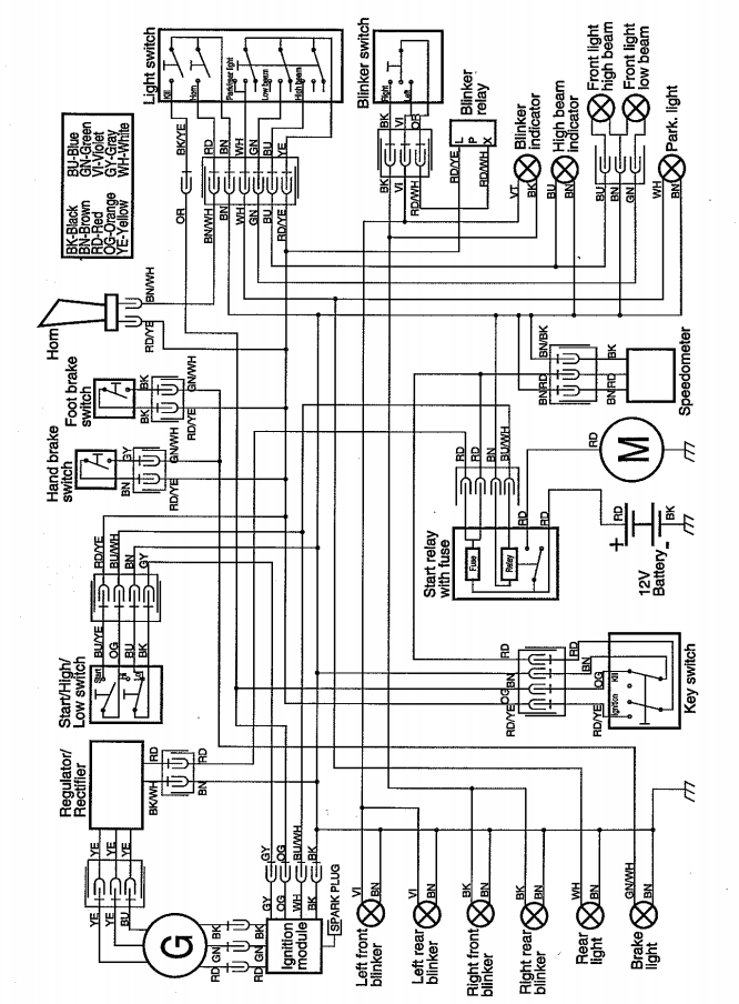
It shows the components of the circuit as simplified shapes and the gift and signal associates between the devices.
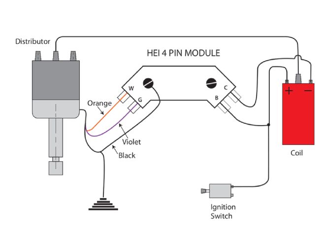
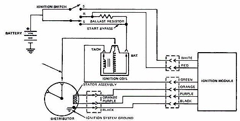
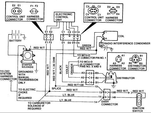
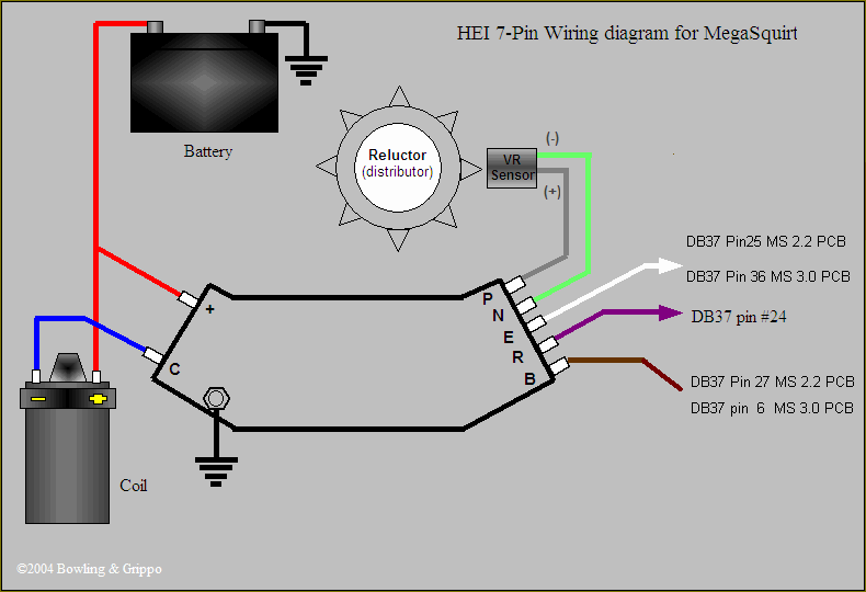
Ignition module wiring diagram. 10 ohm ignition coil metal core spark plug wire and a copper core spark plug gapped at 025. How to test the gm distributor mounted ignition module. Battery starter relay ignition switch electric choke switch carb bowl vent solenoid electric choke heater ignition module coil resistance wire distributor harness ignition coil starter solenoid starter motor and automatic transmission neutral start and back up switch. Gm 4 pin hei electronic ignition control module wiring connectionsdiagram with a magnetic pickup coil.
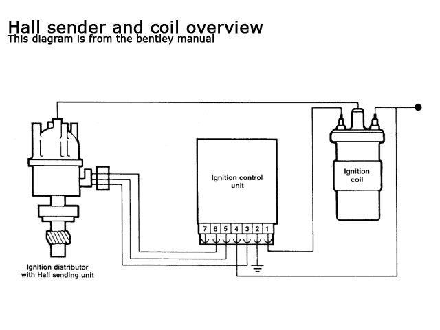
7 pin ignition module wiring diagram wiring diagram is a simplified satisfactory pictorial representation of an electrical circuit. The coil andor module may burn up if the ignition switch is left on for more than 5 minutes with the engine not running. To locate the ignition module refer to a wiring diagram for your vehicles particular make and model. Beginners guide to automotive wiring mopar battery guide 1966 1974 mopar fuse guide 1961 1972 mopar bulb and flasher guide 1961 1971 wiper motor part number guide electronic ignition conversion instructions simplified ignition charging diagram wdual ballast resistor electronic ignition.
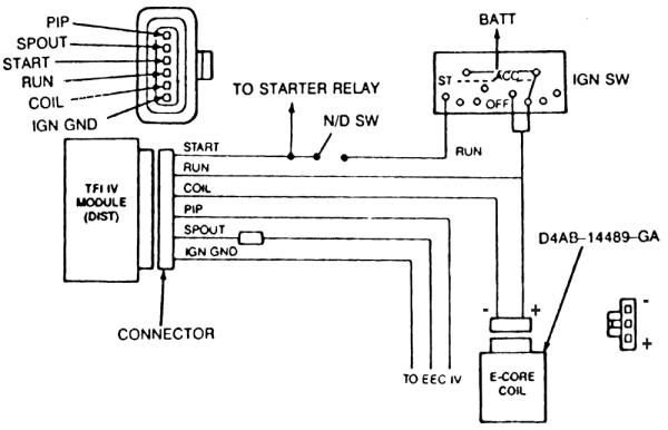
As you might guess the placement can change based on the type of vehicle so it is important to have the correct diagram or you will be practically going in blind. Here is a typical schematic of the 1990 grand wagoneer ignition system wiring diagramthe ignition system consists of. Locate the terminals running into and out of the ignition module. This tutorial will help you test the ignition coil ignition module and the crankshaft position sensor pickup coil.
Placement of the module varies from model to model so check the appropiate service manual of your vehicle for the exact location.


