Instrument Logic Diagram Symbols

Pin On Pipe Diagrams

Electrical Symbols Analog And Digital Logic
Engineering Logic Diagrams Instrumentationtools

Since ladder logic is a graphical programming language the plc programs written in ladder logic are a combination of ladder logic symbols.
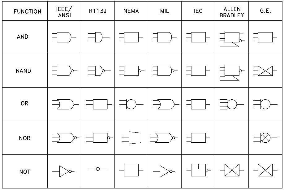
Instrument logic diagram symbols. And fabrication construction and architectural drawings. All the symbols can be found in the standard defining ladder diagram programming. Engineering fluid drawings and prints. The logic symbols called gates depict the operationstartstop circuits of components and systems.
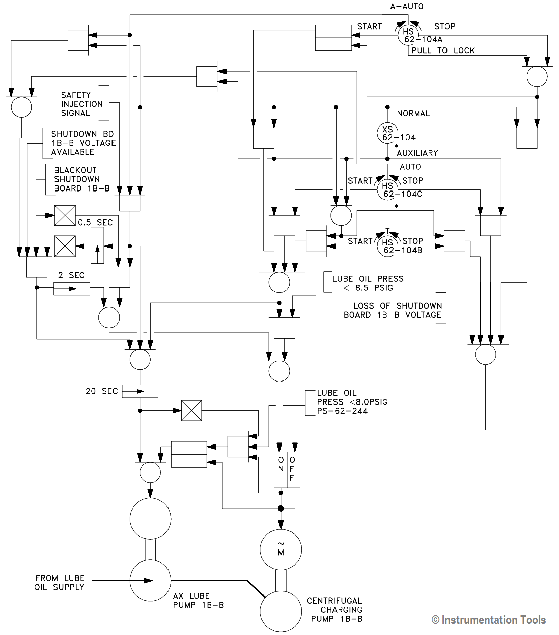
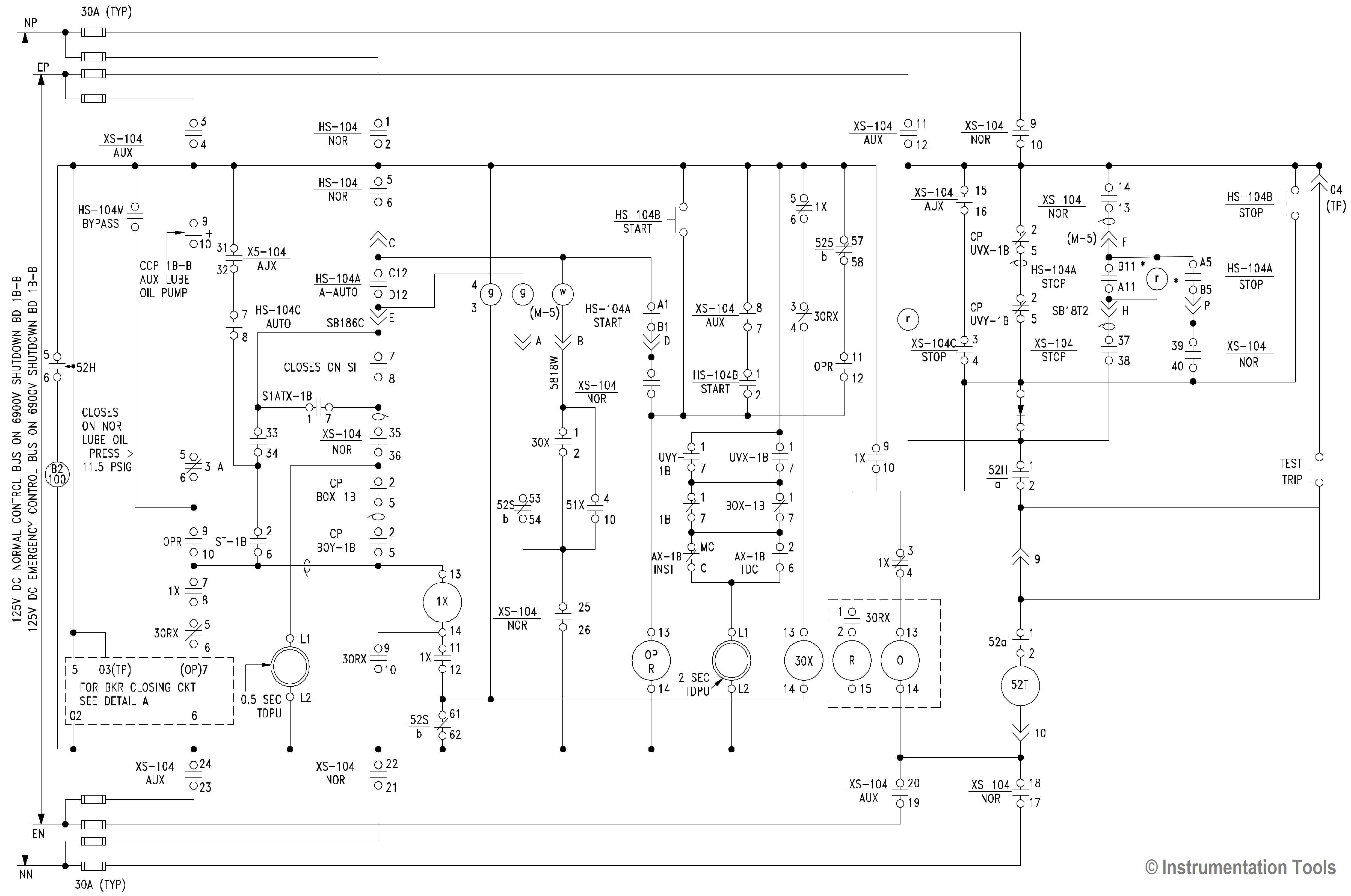
It doesnt matter if it is a level transmitter a flow meter a pressure gauge or some other type of indicator. The following two figures which use a common facility startstop pump circuit as an example clearly demonstrate the reasons for learning to read logic diagrams. Piping and instrumentation diagram pid. 50 diagram contents a.
Electronic diagrams and schematics. Logic circuits and diagrams. Detailed graphical representation of a process. The symbology for the identification of the measurement and control instrumentation on the flow and process diagrams and on the pid piping instrument diagram commonly called pi piping instrumentation is generally compliant with the standard isa instrumentation society of automation identified as s5 that is composed of identification codes and graphic symbols.
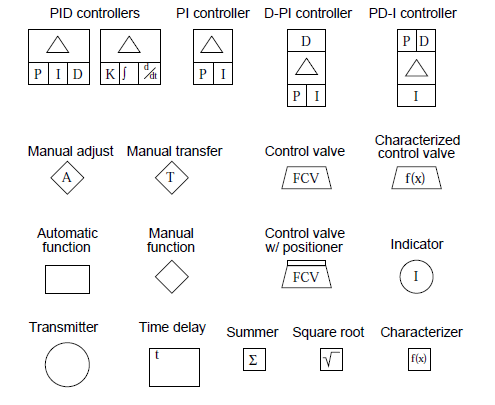
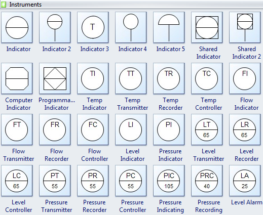
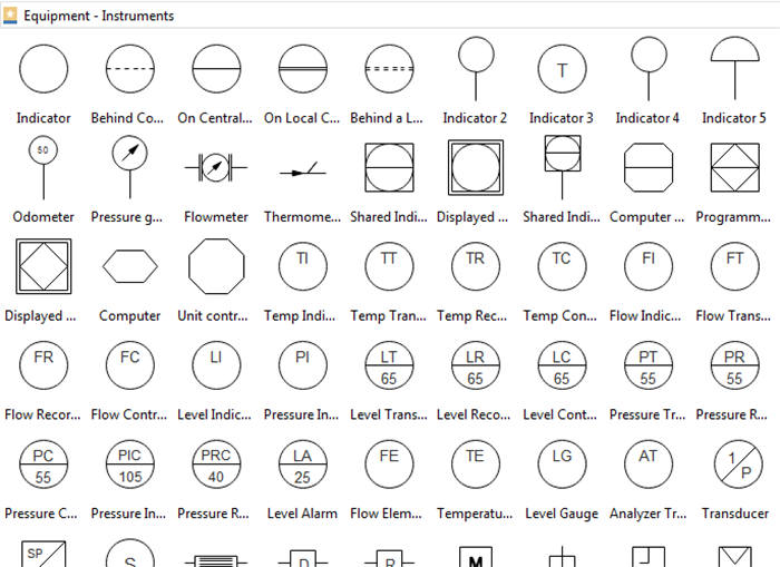
However when we are being specific then any of the specific symbol for the particular flow sensormeter can be used. Common pid symbols used in developing instrumentation diagrams. The symbols and designations are used as conceptualizing aids as design tools as teaching devices and as a concise and specific means of communication in all types and kinds of technical engineering procurement construction and maintenance documents and not just piping and instrumentation diagrams pids. Major symbols and conventions.
Symbols used in control logic diagrams are provided in ansiisa 52 1976 binary logic diagrams. Diagrams instrument index data sheets and vendor drawings. Note that fe is the general symbol for flow sensors in pids. Devices and components to perform a specific operation as a unit.
Facility operators and technical staff personnel commonly see logic symbols on equipment diagrams. A circle symbol is quite simply any physical instrument or device in the field or on a panel. Including the hardware and software ie piping equipment and instrumentation necessary to. Process mechanical engineering systems piping process and instrumentation construction drawings specifications purchase orders manifests and other lists.
Design construct and operate the facility.
Engineering Logic Diagrams Instrumentationtools

Design Elements Instruments Instruments Vector

What Is An Instrumentation Loop Diagram Field

Plc Learning Series 4 How A Ladder Logic Diagram Works
Logic Diagram Sama Wiring Schematic Diagram

Instrumentation Symbols Of The Four General P Id
Engineering Logic Diagrams Instrumentationtools

Logic Diagram Sama Wiring Schematic Diagram
Standard Process Flow Diagram Symbols And Their Usage
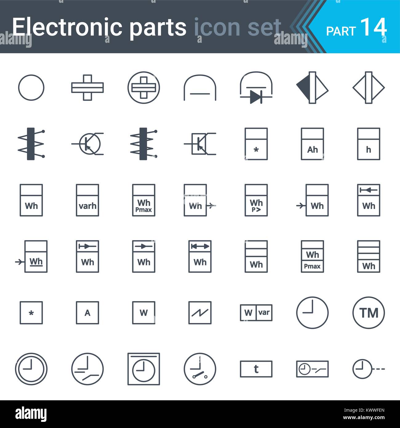
Electronic Schematics Wiring Diagrams Folder
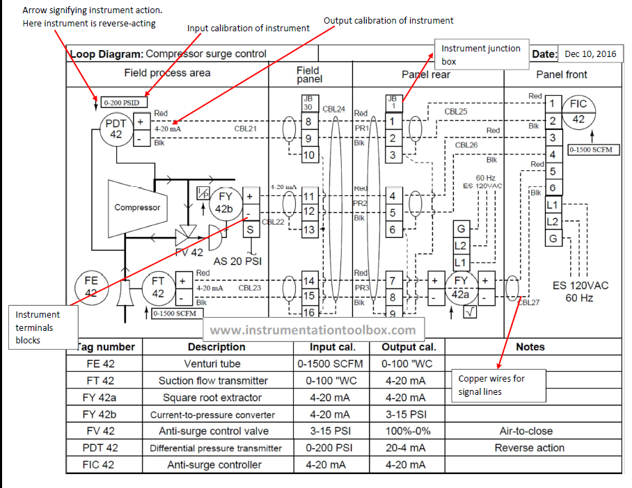
Basics Of Instrument Loop Diagrams Learning

Common P Id Symbols Used In Developing Instrumentation

Logic Diagram Instrumentation Online Wiring Diagram
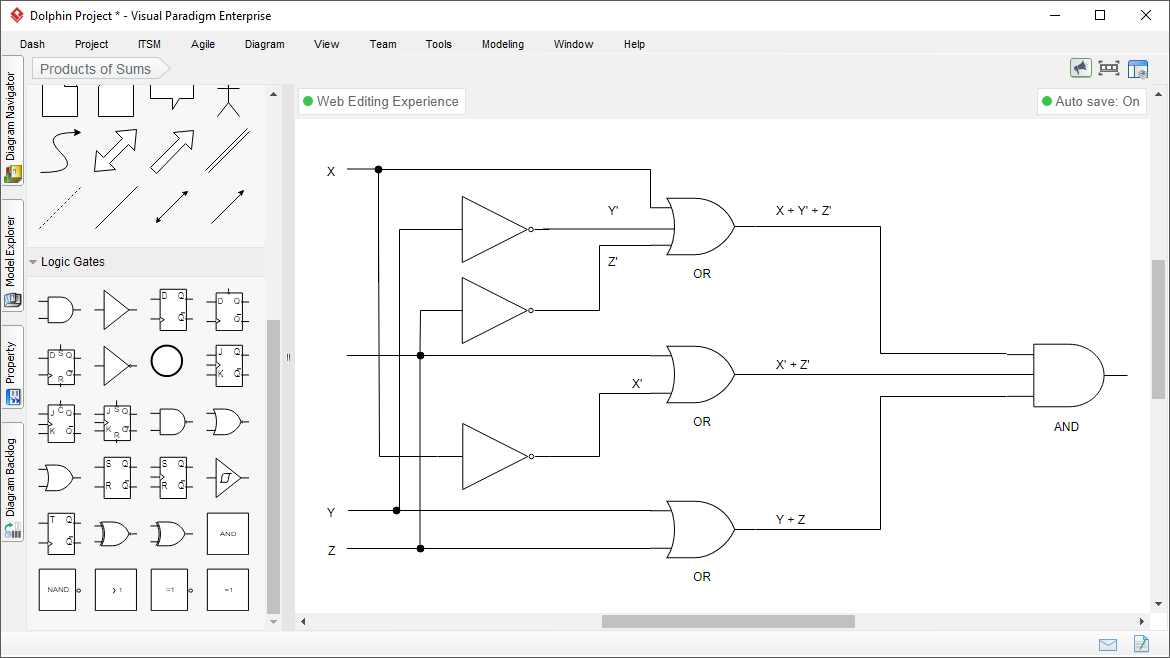
Diagram Instrument Logic Diagram Full Version Hd Quality

Piping Diagram Legends List Of Wiring Diagrams

How To Read A Schematic Learn Sparkfun Com
How To Read Piping And Instrumentation Diagram
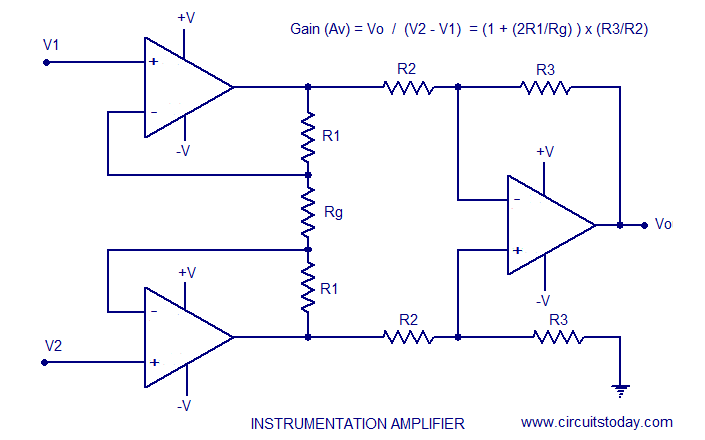
Instrumentation Amplifier Using Opamp Circuit Diagram
