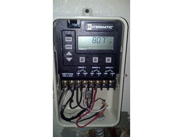
Intermatic Pool Timer Wiring

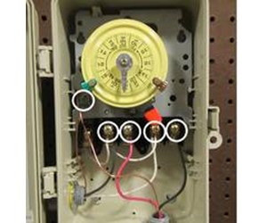
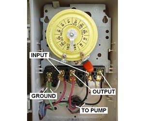
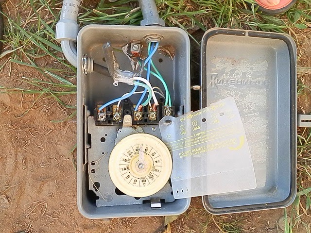
Variety of intermatic pool timer wiring diagram.
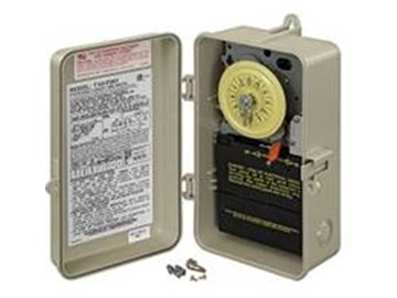
Intermatic pool timer wiring. Simple reliable solutions for any location. You know that the intermatic wire order so it is just a matter of matching the wires up as the other timer. Watch how to instruction videos. From programmable time controls to photocontrol sensors to weatherproof covers intermatic offers the most robust lineup.
Search our new and improved image library for images of intermatic products. It reveals the components of the circuit as streamlined forms and also the power as well as signal connections in between the devices. A t104 timer is used for 230v supply voltage. Some electric companies charge higher rates for electricity used during on peak hours.
A wiring diagram is a simplified traditional pictorial representation of an electrical circuit. Bailey line road 323942 views. Variety of intermatic 240v timer wiring diagram. Browse intermatics general catalog pool spa catalog grasslin catalog and specification guide.
View instruction manuals wiring diagrams product brochures and sell sheets. A wiring diagram is a simplified standard pictorial depiction of an electrical circuit. The timers motor taps into the wires that enter the unit. After passing the on tripper the pump motor runs until the dial passes the off tripper.
The intermatic pool timer uses a 24 hour dial with at least two adjustable trippers that activate the pool pump. Note timers vary with supply voltage. Wiring for model t103 intermatic timer. Installing an intermatic t104 timer is a great way to dramatically reduce run time and energy costs.
The pump remains off until the dial reaches the next on tripper. It shows the components of the circuit as simplified shapes as well as the power as well as signal links in between the devices. An intermatic timer switch saves electricity when it turns a water heater off at night and when it limits the amount of time a pools filtration system runs.


