Plc Motor Control Circuit Example

Basic Plc Program For Control Of A Three Phase Ac Motor
Basic Plc Program For Control Of A Three Phase Ac Motor
Plc Program For Motor Starter Plc Motor Control Circuit
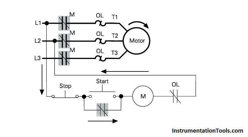
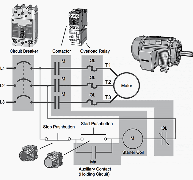
The project starts with converting a motor control circuit to a plc circuit in plc relay logic.
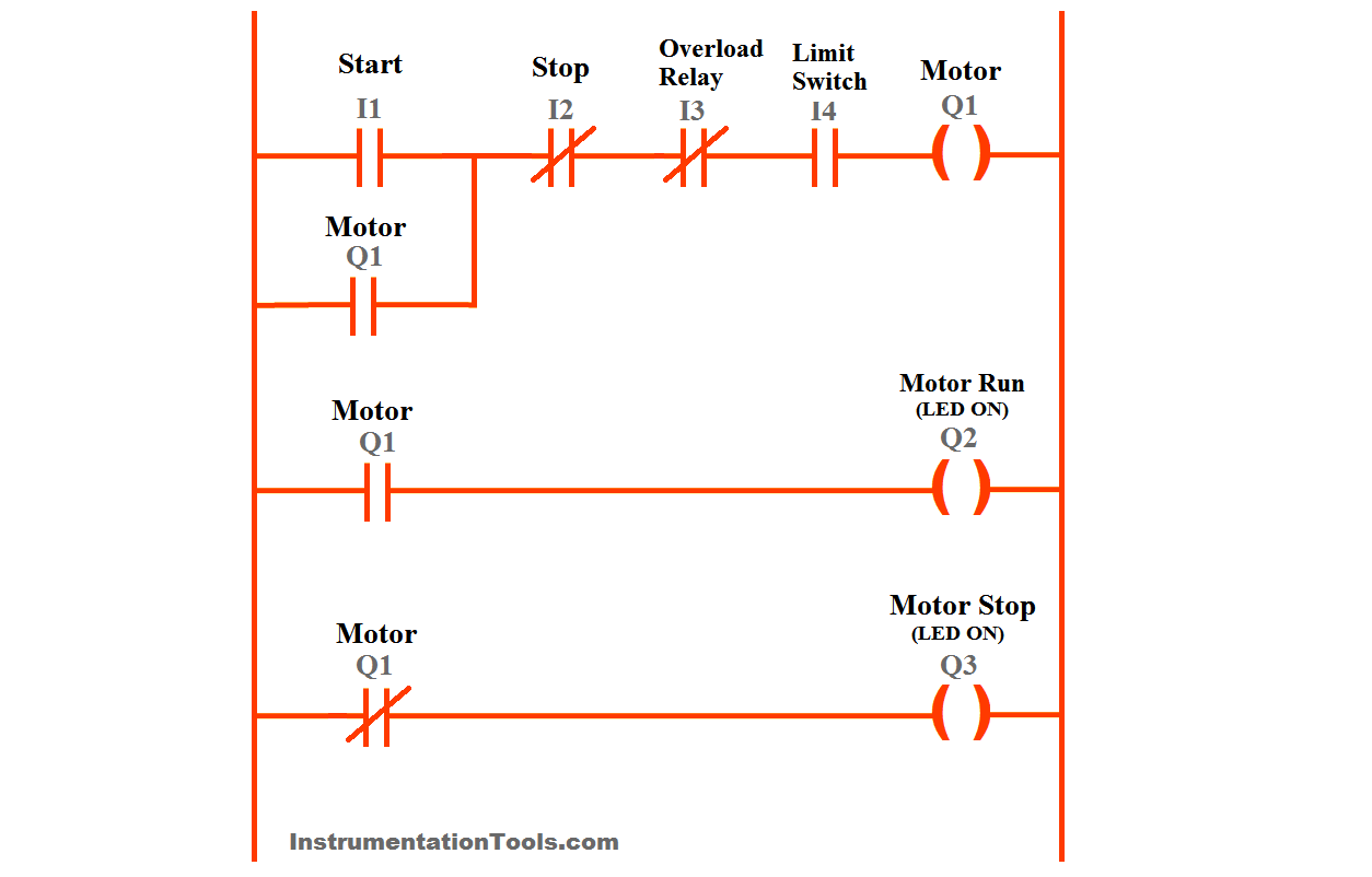
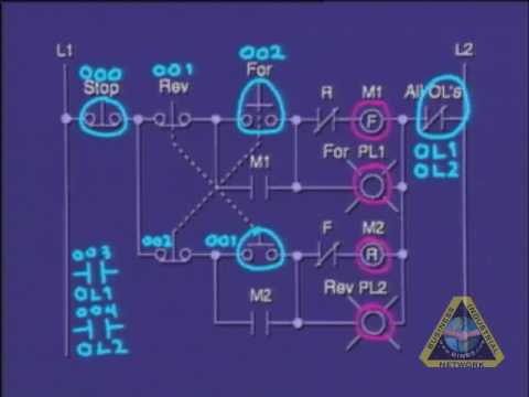
Plc motor control circuit example. Discuss about plc motor control circuit example using ladder logic. The history of programmable logic controllers. Plc program for motor starter. Or logic is a logic circuit that contains two or more control devices for one load as seen in figures 3 and 4.
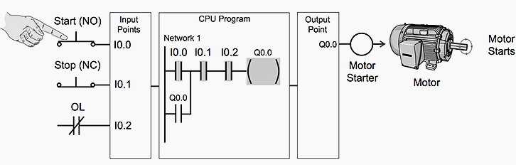
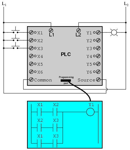
Discrete control using programmable logic controllers chapter 9. If the input wiring for x2 the stop switch were to fail open there would be no way to stop the motor. Home technical articles basic plc program for control of a three phase ac motor for beginners motor starter while the lighting control system previously discussed is useful to explain basic plc operation a more practical and only slightly more complex application is start stop control of an ac motor. Programmable logic controllers plc chapter 6 ladder logic.
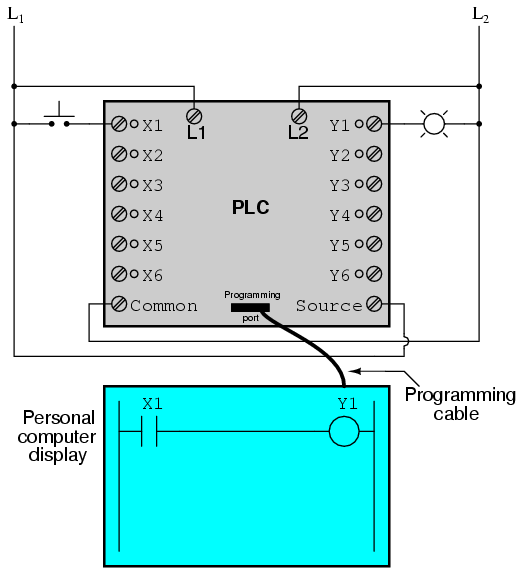
In this motor control circuit example we have a problem. The control devices of an or circuit are connected in parallel with each other and in series with the load. Hard wiring schematic and circuit. A motor controlled by stop and start push button switches.
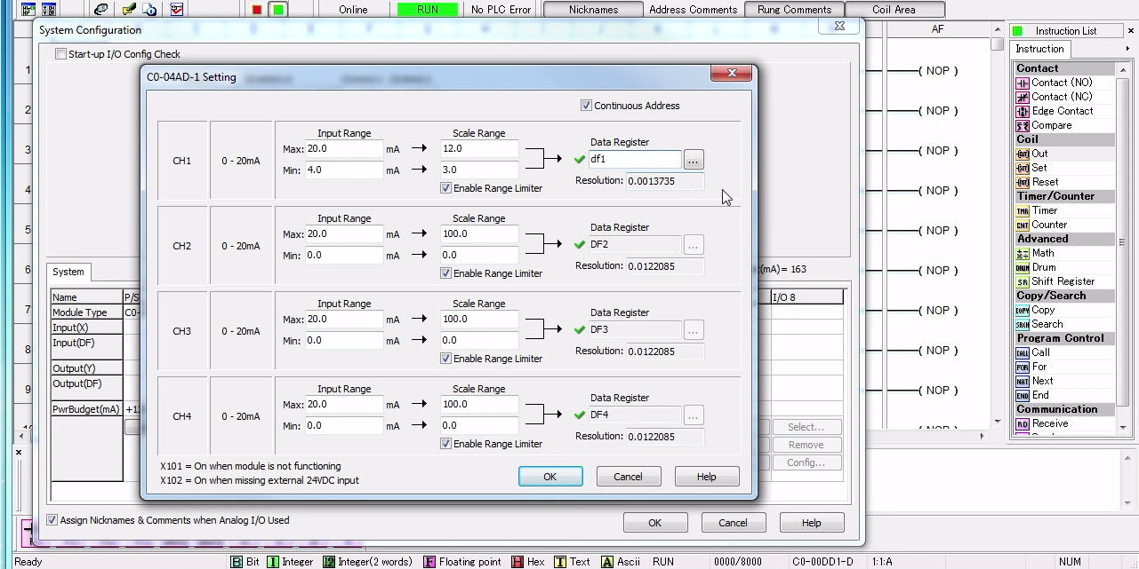
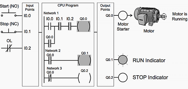
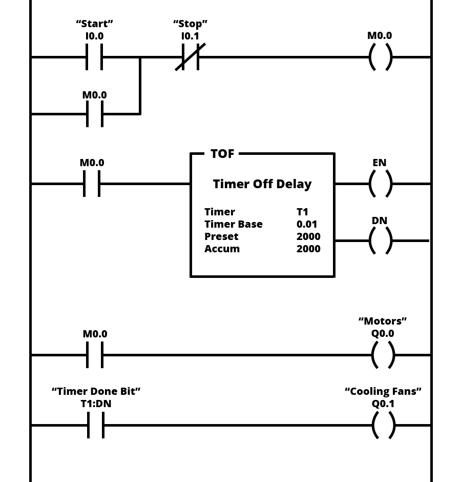
We have another interlock which is overload trip this input is taken from the motor feeder. In our example we consider vibration signals as fail safe so default status is normally closed if high vibration appears then the contact become normally open plc tripsstops the motor. We could replace the push button switches with toggle. The ladder logic for a stardelta motor control is quite simple and that is one of the advantages of using a plc for motor control.
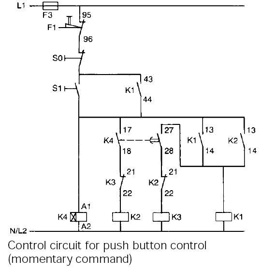
Ladder diagram of stardelta starter with a mitsubishi plc another great example of how to use a plc for stardelta start of an ac motor is example 5 in the pdf file below. One signal light must be. Plc program and circuit. Plc can be reprogrammed.
Programming a plc is easier than wiring a relay control panel. Plcs take less floor space. This video will walk you through the physical wiring of a 3 wire control circuit for a 3 phase motor starter. If we wanted to keep the motor running even after the operator takes his or her hand off the control switches we could change the circuit in a couple of different ways.

Plc Program For Motor Control In Ladder Logic Plc
Basic Plc Program For Control Of A Three Phase Ac Motor

Plc Program For Motor Control In Ladder Logic Plc
Programmable Logic Controllers Plc Ladder Logic

Plc Motor Control Ladder Logic Programming Motor Control
Ladder Logic Examples And Plc Programming Examples

Plc Ladder Logic Symbols Motor Control Circuits In 2019
Programmable Logic Controllers Plc Ladder Logic
Basic Plc Program For Control Of A Three Phase Ac Motor
Plc Program For Motor Starter Plc Motor Control Circuit
Plc Tutorial Plc Program Of Motor Control Circuit

Ladder Logic Examples And Plc Programming Examples

Need Help With The Circuit Of An Ac Motor And The Plc Plcs

How To Convert A Basic Wiring Diagram To A Plc Program
Typical Circuit Diagram Of Star Delta Starter Plc Plc

Basic Plc Layout

Plc Control Systems Automation Introduction
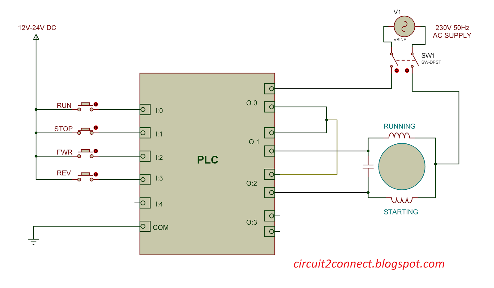
Single Phase Induction Motor Direction Control Using Plc V3
