Pneumatic Solenoid Valve Wiring Diagram
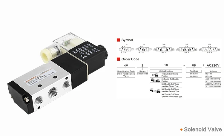
4v110 06 Airtac Solenoid Air Valve Wiring Diagram 4v210 08 With Coil 24v Buy Pneumatic Solenoid Valve 5 2 Way Solenoid Valve Pneumatic Air Valve

Air Valve Wiring Diagram Wiring Schematic Diagram
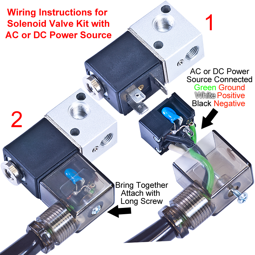
Solenoid Valve Wiring
Directional air control valves are the building blocks of pneumatic control.
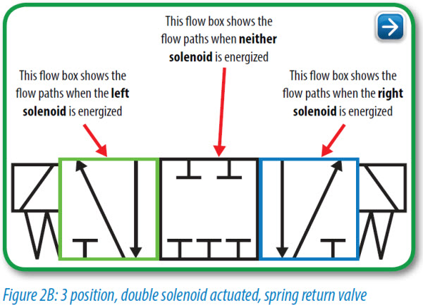
Pneumatic solenoid valve wiring diagram. Pneumatic circuit symbols representing these valves provide detailed information about the valve they represent. Hydraulic solenoid valve wiring diagram gas solenoid valve wiring diagram best solenoid symbol diagram wiring diagrams schematics for hydraulic. Symbols show the methods of actuation the number of positions the flow paths and the number of ports. It shows the parts of the circuit as simplified forms and the power and also signal connections between the devices.
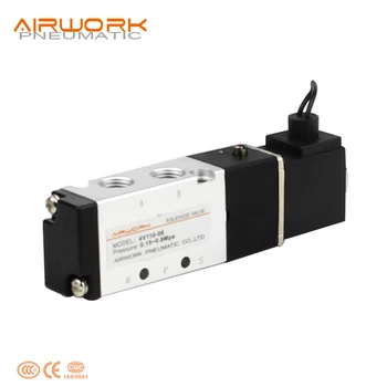
How to use a pneumatic cylinder. Understanding ansi iso schematic symbols for fluid power and pneumatic components are used to identify and graphically denote the function and operation of piped control systems. The spring symbol defines the valve position at rest. Asco valves have a solenoid mounted directly on the valve body.
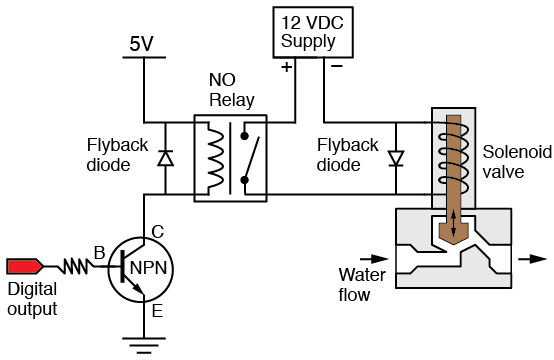
A wiring diagram is a simplified standard pictorial depiction of an electric circuit. A solenoid valve is a combination of two basic functional units. You can also choose from brass alloy and stainless steel. A wide variety of solenoid valve wiring diagram options are available to you such as high pressure low pressure.
Solenoid valve and common pneumatic system symbols. Smc type high quality fittings aq340f 04 00 o d 4mm quick exhaust. Solenoid valve wiring schematic free wiring diagram. 2 port solenoid valve.
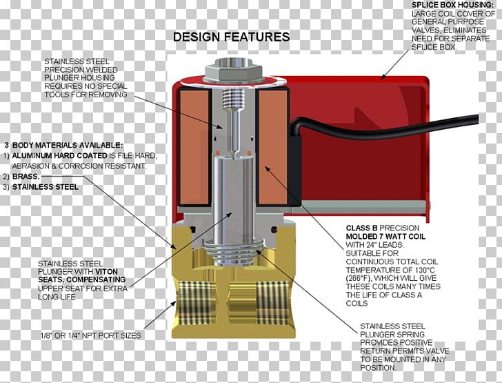
Pneumatic circuit symbols explained. Collection of hydraulic solenoid valve wiring diagram. Assortment of solenoid valve wiring schematic a wiring diagram is a streamlined traditional pictorial representation of an electric circuit it reveals the elements of the circuit as simplified forms as well as the power as well as signal connections between the devices. A solenoid electromagnet with its core a valve body containing one or more orifices flow through an orifice is shut off or allowed by the movement of the core when the solenoid is energized or de energized.
Smc valve bank wire diagram. About 72 of these are valves 14 are pneumatic parts and 8 are machinery engine parts. Smc solenoid valve wiring diagram gallery smc type high quality fittings aq340f 04 00 o d 4mm quick exhaust. How to wire a din plug for solenoid coil duration.
2 a is pressurized and b is exhausted. Solenoid valve electrical connection procedure. Assortment of smc solenoid valve wiring diagram.
Pneumatic Circuit Symbols Explained Library Automationdirect
Airtac Type 4v210 06 4v210 08 5 2 Way Solenoid Valve Wiring Diagram Pneumatic Air Valve 12v Buy Pneumatic Solenoid Valve 5 2 Way Solenoid

Ussolid 1 4 5 Way 2 Position Pneumatic Electric Solenoid Valve Dc 24 V

Six Secrets About Pneumatic Directional Solenoid Valve
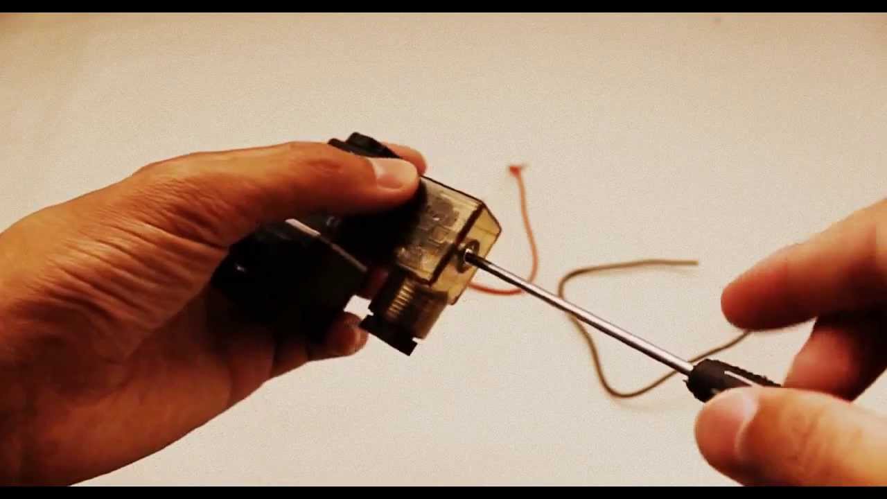
Solenoid Valve Electrical Connection Procedure

Air Solenoid Valve Diagram Wiring Diagrams
Ideal Vacuum New Solenoid Valve Kit For Kf10 Kf50

24vdc Airtac Solenoid Valve 4v210 08 Manual Wiring Diagram 4v210 08 Buy High Quality Pneumatic Solenoid Valve Pneumatic Solenoid Valve 4v210

Solenoid Schematic Wiring Schematic Diagram

3 2 Way Pneumatic Valve Tameson

Lee Solenoid Valve Drive Circuit Schematics The Lee Company
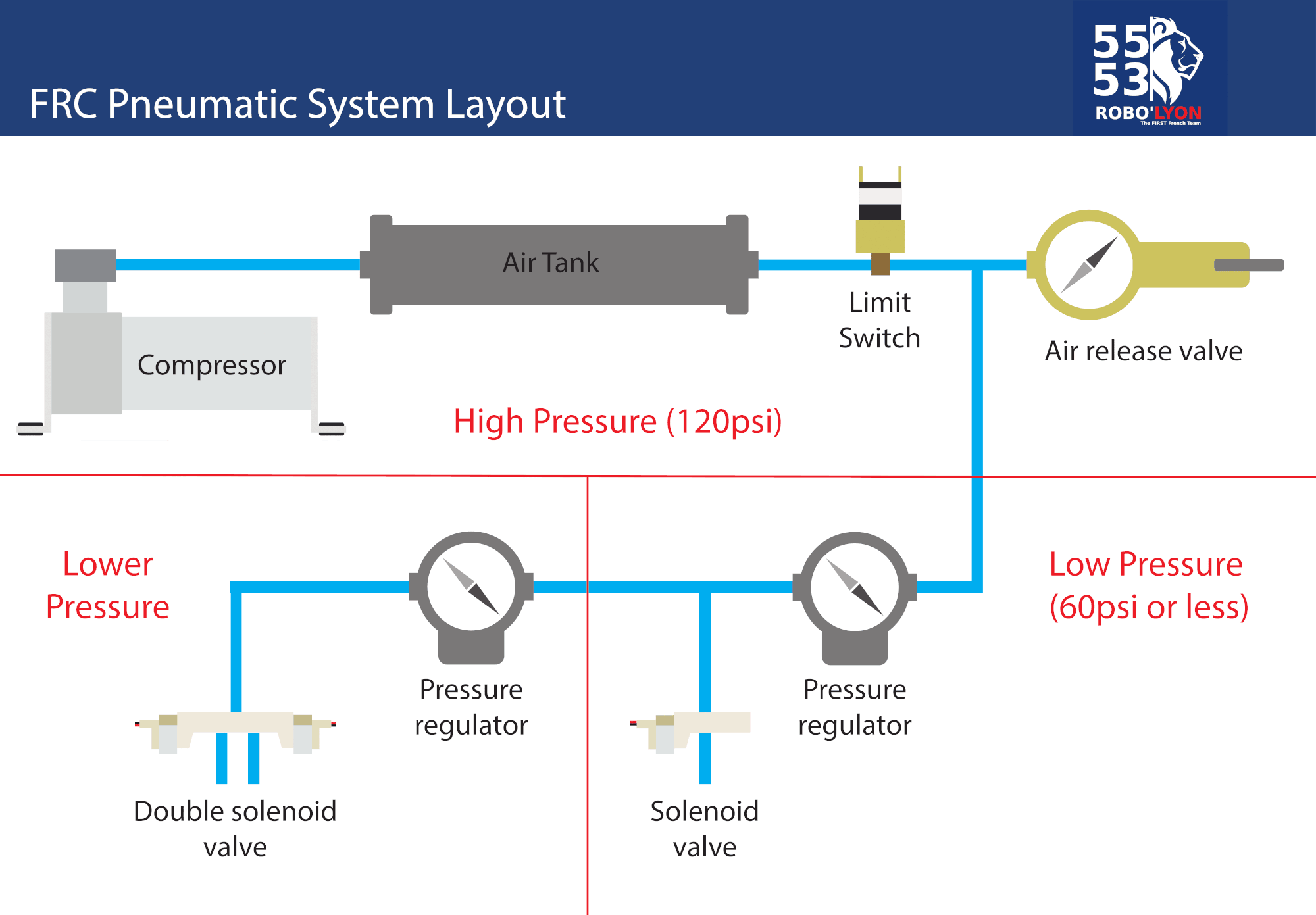
Frc Pneumatic System Diagram Control System Chief Delphi
Solenoids U70 G70 Series Mc Hi Tech Controls Camozzi
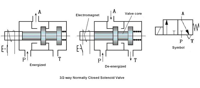
How Does 3 2 Way Pneumatic Solenoid Valve Work

Airtac Type 4v210 08 5 2 Way Solenoid Valve Wiring Diagram Pneumatic Air Valve Buy Pneumatic Solenoid Valve 5 2 Way Solenoid Valve Pneumatic Air
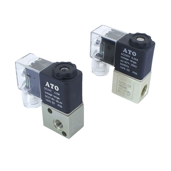
Pneumatic Solenoid Valve 3 Way 12v 24v 110v 220v

Numatic Engineering

Frc Pneumatics Diagram Wiring Diagrams
