Proces Flow Diagram Lng Plant

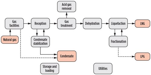
6 Block Flow Diagram Of An Lng Plant Download Scientific
Process Flow Diagram Lng Plant Wiring Diagram Database

Lng Plant Flow Chart Youtube

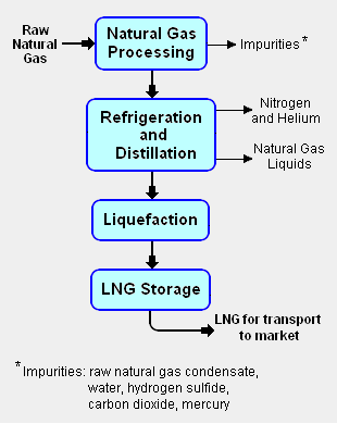
Block diagram of lng plant main process stages liquefaction process technologies examples from hammerfest lng plant examples from other lng plants.
Proces flow diagram lng plant. Chart standard and modular liquefaction plants and associated process technology enable displacement of liquid fuels through small and mid scale lng. Process selection is critical to onshore lng economics world oil magazine. Cascade process for natural gas liquefaction methane ethylene propane ng 32 12 0c 14 bar 7. Charts nitrogen cycle liquefaction technology is simple to operate and eliminates the the need for hydrocarbon refrigerants which makes it ideal for remote areas.
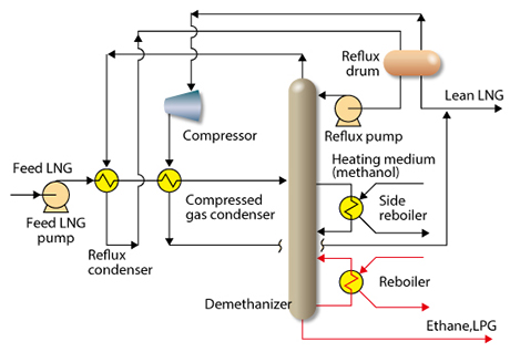
Figures 65 and 66 show simplified process flow diagrams for the plant for the mechanical drive and electrical power options respectively. The major equipment components of an lng import and regasification terminal are. Simplified lng plant block diagram end flash hhc extraction ch 4 n 2 fuel gas power heat. The lng plant all mechanical drive or all electrical power.
Valerie rivera created date. A typical lng import terminal process flow diagram is shown in figure 5. Licensed to youtube by umg on behalf of hollywood records. The natural gas liquefaction plant step two in the process chain is cleaning the natural gas at the liquefaction plant.
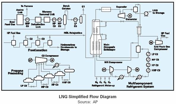
Animation showing how woodside produces liquefied natural gas lng for customers in the asia pacific region and beyond. Lng liquefied natural gas basics. Liquefied natural gas lng for the 2014 spe roughneck camp chris caswell director lng and flng. Flow diagram for a typical lng plant.
Pedl warner chappell umpi walt disney music company publishing amra bmi broadcast music inc and 8. From plant to plant the lng process woodside energy. Table of content. Lng plant animation.
Not all lng plants are created equal nalpace offshore liquefaction flng significantly increases the. Lng j t expander bypass valve lng lng flash tank lng lng lng liqueed methane gas to sub cooler j t expander bypass valve compressor anti surge valve main cryogenic heat exchanger on site ccgt power plant provides electric power for compressor drives and steam for heating processes lng liquefaction process flow diagram. The following sections describe the processes noting where they are common to both powering options. Combustible mixture of hydrocarbons.
Lng plant overview seminar with supplier association murmanshelf murmansk 15 may 2012 jostein pettersen.
Process Selection And Recent Design Innovations For Lng

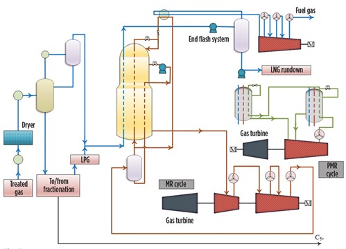
Simplified Process Flow Diagram Of Ap X Lng Process
Showcontent
Chpt 4 Natural Gas And Lng Tech
Process Selection And Recent Design Innovations For Lng
Ogf Article Will Lng Plants Meet A Growing Demand For Clean

Lng Plant And Regasification Terminal Operations Sciencedirect

Fig 1 Lng Block Flow Diagram Ppt Video Online Download
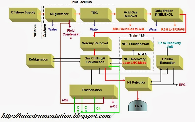
Tn Instrumentation Lng Process Block Diagram And Key Process

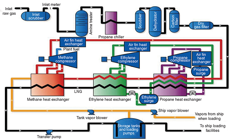
Optimized Cascade Process Conocophillips Lng Technology

Lng Plant And Regasification Terminal Operations Sciencedirect
Process Selection And Recent Design Innovations For Lng

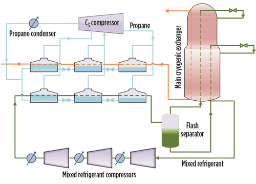
Schematic Representation Of Lng Plant C 3 Mr Liquefaction
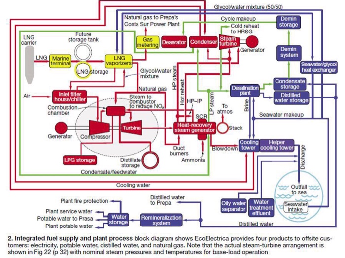
Solved A Name Of The Power Plant B Flow Diagram Of The
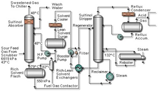
Sulfinol Netl Doe Gov

Air Heater Design For Lng Regasification Terminal Free
Coreflux Cold Reflux Technology Toyo Engineering Corporation
Liquefied Natural Gas Encyclopedia Article Citizendium
