Protective Relay Wiring Diagram For Ge

5a 5c 5d 5e and 5f and channel arrangements that may be ordered for the relay.
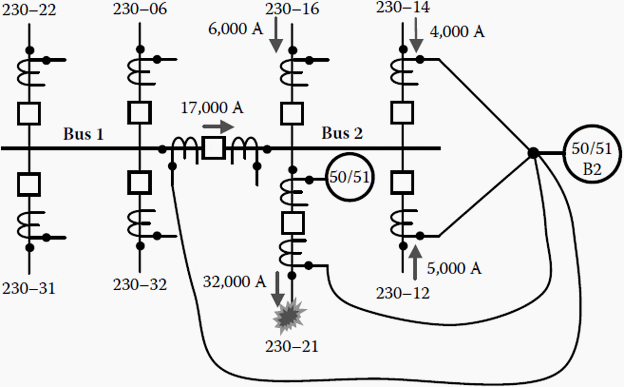
Protective relay wiring diagram for ge. When the device is programmed as a sr750 850 actual values cannot be retrieved from note. 4 each measuring board has a built in power off memory feature for the time delayed and instantaneous led indicators. Ground fault protection in three wire equipment ground fault protection can be provided for 3 wire and 4 wire equipment fed from a solidly grounded 4 wire supply wye or delta. Of these relays are intended for use as fault protective or regulating devices.
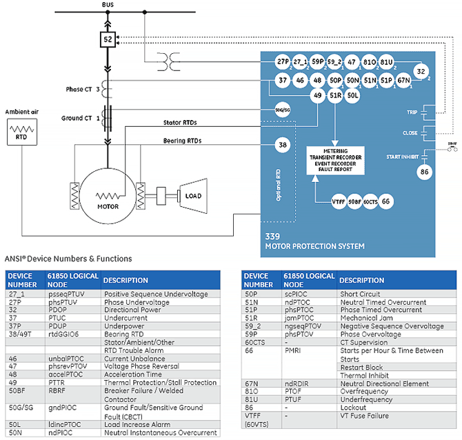
Thermal motor protection models give the sel 710 advanced protection beyond industry standards. 3 a guide to the application. View and download ge multilin 850 instruction manual online. See the 8 series protective relay communications guide for the list.
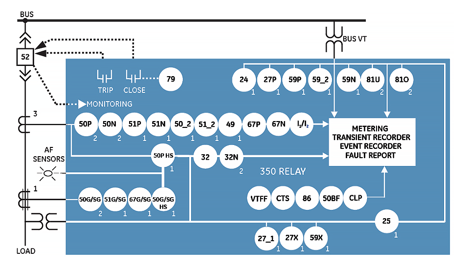
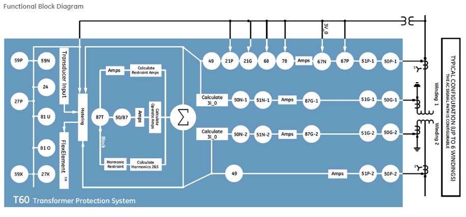
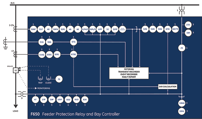
Modified differential scheme with gf. Typical wiring diagram. Wherever a tilde symbol appears substitute with the slot position of the module. Connections the internal wiring diagrams for the various relays covered by these instructions are shown in.
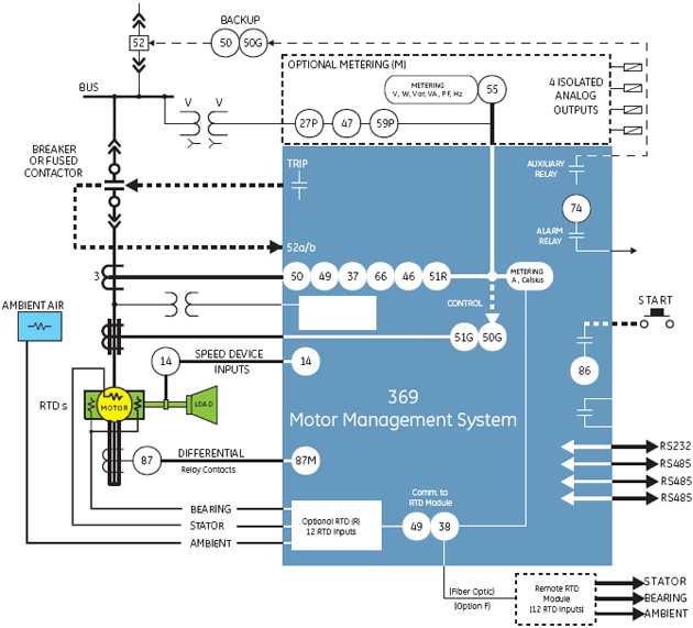
Power relays application guide ge power management. Application diagrams are provided in figures 2 to 8 inclusive showing typical wiring configurations. This premiere motor protection scheme allows maximum start times. Diagram 177 derivation of relay current and voltage 176 effect on distance relays 181 generator protection 218 trip blocking relay 304 390 tripping relay 361 low tension current for distance relays 356 low tension voltage for directional relaying 386 for distance relaying 148 352 general 145 magetizing current inrush effect on.
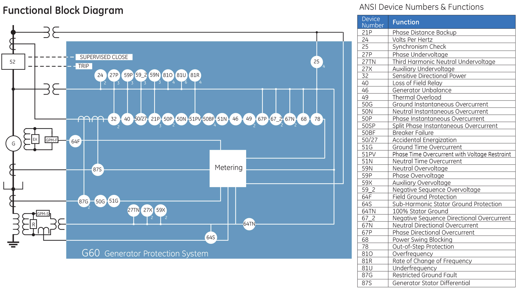
Our solutions continue ges century long tradition of power system innovation. This makes the relays particularly. The relay should be mounted on a vertical surface. Transducer inputoutput module wiring ge multilin g60 generator protection system 3 23.
Facilitate inspection and testing. Tripping and control relays figure 1 mvaj 05 relay features directly operates circuit breaker. Typical applications are given complete with all the different wiring diagrams and tables listing all the individual ratings of the five different relays. From generators to transmission lines to motors and beyond we ensure dependable safe power worldwide.
Inception of an earth fault on battery wiring. The protective relay may trip a circuit breaker directly or according to the coil rating and the number of circuits to be energised. The relay can be used to provide selective protection for overhead and underground distribution. Pioneering key principle advancements over the last 100 years ge continues to lead the way making new protection control and automation applications possible.

