Residential Electrical Schematic Wiring Diagram Circuit

For example a stick frame home consisting of standard wood framing will be wired differently than a sip or structured insulated panel home because of access restrictions.
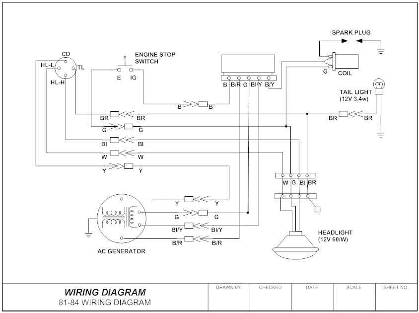
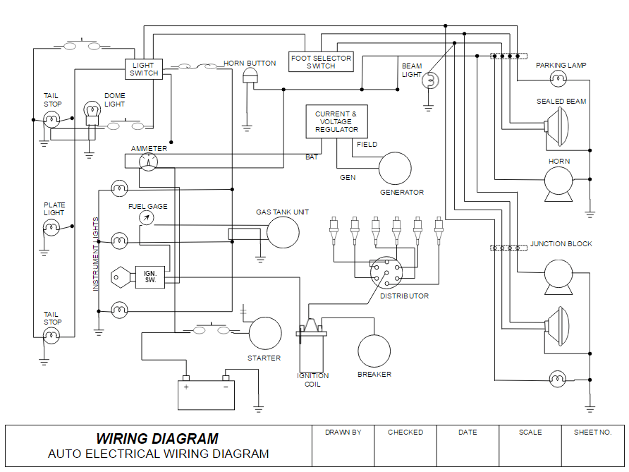
Residential electrical schematic wiring diagram circuit. It shows the components of the circuit as simplified shapes and the power and signal connections between the devices. Ground fault circuit interrupter wiring diagrams diagrams for gfci receptacles including protection for duplex receptacles in the circuit and the gfci at the end of the circuit. Electrician offers house wiring diagrams connections tutorial diagrams and instruction for restoring correct hook ups in electrical boxes and for outlets switches and lights. An electrical wiring diagram can be as simple as a diagram showing how to install a new switch in your hallway or as complex as the complete electrical blueprint for your new home.
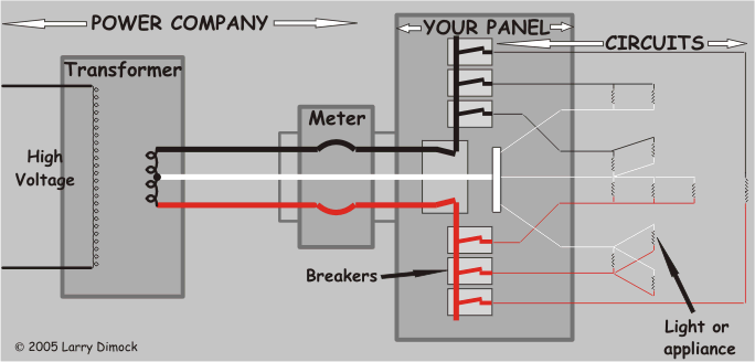
A wiring diagram usually gives information about the relative position and arrangement of devices and terminals on the devices to help in building or servicing the device. Residential electric wiring diagrams are an important tool for installing and testing home electrical circuits and they will also help you understand how electrical devices are wired and how various electrical devices and controls operate. Power comes from the feeder lines into the main breaker usually the topmost breaker in the panel which is usually rated at 100 or 200 amps. A wiring diagram is a simplified conventional pictorial representation of an electrical circuit.
Electric circuits like ac lighting circuit battery charging circuit energy meter switch circuit air conditioning circuit thermocouple circuit dc lighting circuit multimeter circuit current transformer. Various branch circuits that make up a residential electrical wiring system. The circuit detective home electrical troubleshooting. This is unlike a schematic diagram where the arrangement of the components interconnections on the diagram us.
From there individual breakers then distribute power and provide overload protection for. The one line diagram is similar to a block diagram except that electrical elements such as switches circuit breakers transformers and capacitors are shown by standardized schematic symbols. Residential electrical wiring diagrams summary. A one line diagram or single line diagram is a simplified notation for representing an electrical system.
Circuit breaker wiring diagrams wiring for a breaker box a gfci breaker as well as 15 20 30 and 50 amp circuit breakers. An electric circuit is a closed loop with a continuous flow of electric current from the power supply to the load. Illustrated wiring diagrams for home electrical projects.


