Rs485 Cable Connection Diagram

Rs 485 Connections Faq 2 Wire Rs485 Rs232 B B Electronics

Rs 485 Connections Faq 2 Wire Rs485 Rs232 B B Electronics
.aspx)
Rs 485 Connections Faq 2 Wire Rs485 Rs232 B B Electronics
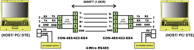
The txd and txd lines carry transmit data while the rxd and rxd contain the receive data.
Rs485 cable connection diagram. Briefly discussed in their simplest form as they relate to rs 485. The rs485 system used for modbus communication provides a main cable bus or backbone to which all the devices have to be connected with branches also known as stubs that are as short as possible. Controlsoft recommends using a slot head screwdriver with a blade 332 wide suitable for size 0 or 1 screw. Figure 4 is a pin diagram for both 25 pin rs485 pinout half duplex and full duplex pinout connectors.
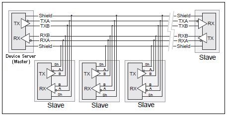
The are no bias nor terminator resistors in the net. A terminating resistor is simply a resistor that is placed at the extreme end or ends of a cable figure 4. Unlike what happens in many energy distribution systems the manner in which the devices are connected in parallel is important. Cable termination rs485modbus rtu line termination resistor to minimize the reflections from the end of the rs485 cable it is required to place a line termination near each of the 2 ends of the bus modbus specifies that a network not requiring line bias shall use a 120w w resistor between the differential pair.
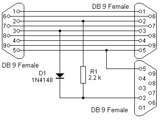
If you are operating anywhere near these values you must arrange your wiring close to the ideal. Rs232 pinout rs232 pinout standards exist for both db9 and db25 connectors as shown below. Check the data sheet schematic or block diagram. Db25 signal db9 definition 1.
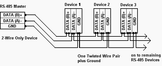
The is no ground connection because the rs485 232 converter doesnt have a ground terminal. All devices with rs485 port have a shield terminal which may be connected to the chassis ground eg. On 7x50 880 8600 or to the isolated reference of the rs485 port ie. But controllers do have.
Wiring rs 485 networks to wire the connections carefully strip about 14 of the conductor insulation insert the bare conductor into the correct terminal orifice and then fasten the screw. Rs485 can handle speeds of over 10 mbits per second and line lengths of over 1 km. Figure 3 is an rs485 wiring diagram for rs485 pinout db9 connectors. No connection to the chassis ground as in 6200 6300 6100 2.
A rs 422 device does not tri state the transmitter so it cannot use these connections. The cable used is a profibus shielded 2 wires not twisted the converter has a built in terminator resistor and it is enable. The value of the terminating resistor is ideally the same value as the characteristic impedance of the cable. In all devices the rs485 ports are opto isolated from the internal device electronics.
9 Rules For Correct Cabling Of The Modbus Rs485
Troubleshooting Rs485 Connections

4 Wire Rs 485 To Fiber Connections Fostcdr B B Electronics

Connecting An Egx150 To A Serial Rs485
Rs 485 Pins For 2 And 4 Wire Transmission National
Understanding Rs485 Wiring Connection Monitoring Software

Wiring Of Rs485 Communications Networks
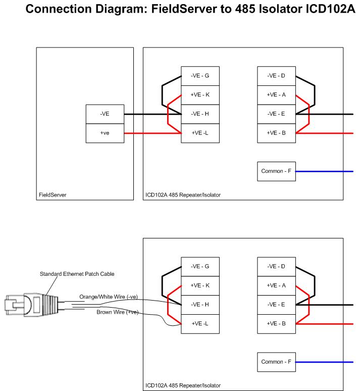
Fieldserver 485 Connection Diagram To Isolator Icd102a

Rs485 Interface Rs485 Pin Diagram

Rs485 Communication Wiring Diagram For A Momentum Processor
Rs 485 Basic Pinout Diagram
Rs 485 Cable Specification Guide

Rs485 Communication Wiring Diagram For A Momentum Processor
Rs485 Cable Diagram List Of Wiring Diagrams
Understanding Rs485 Wiring Connection Monitoring Software

Dgh Data Acquisition Usb Comi Rs 485 Connection Diagram

Rs 485 2wire Diagram Schematics Online
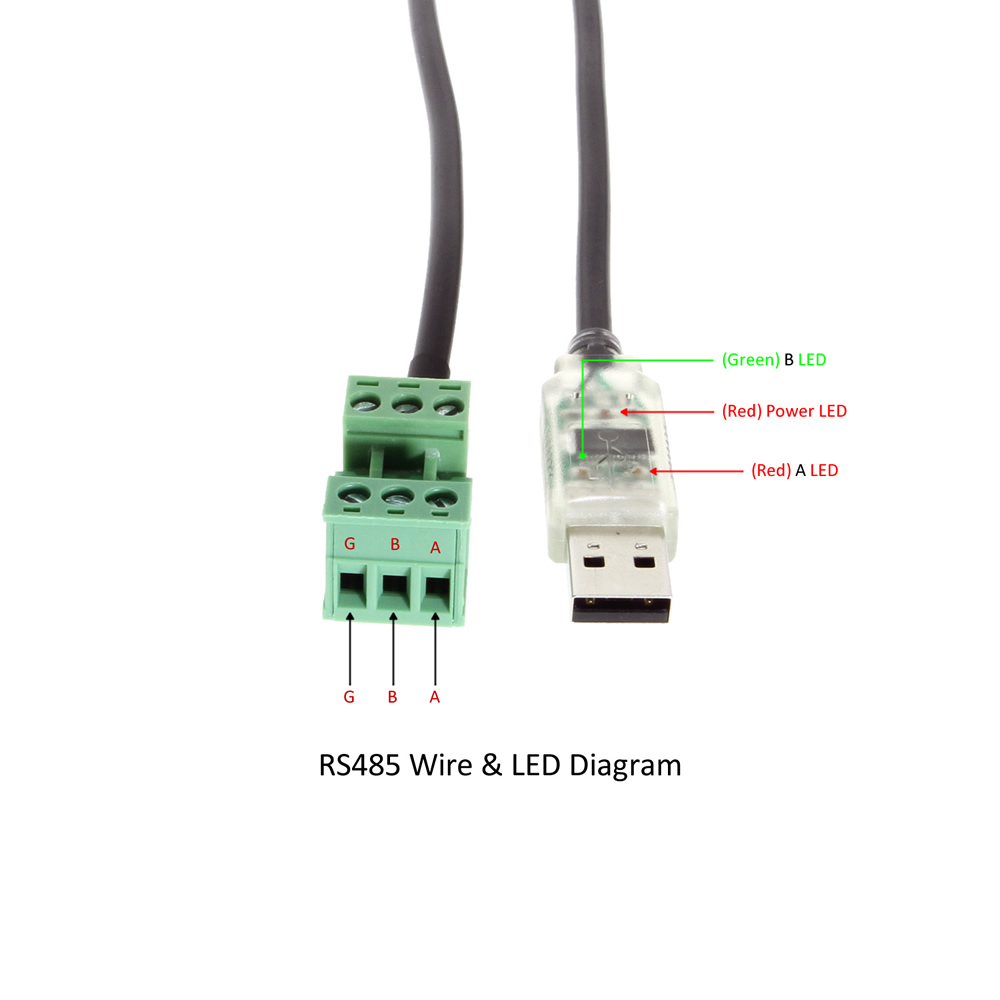
Usb To Rs485 Compact Ftdi Converter With Terminal Screw
