Sending Unit Wiring Diagram

If the readings are good on the sending unit check your continuity of the ground of the tank and sending unit.
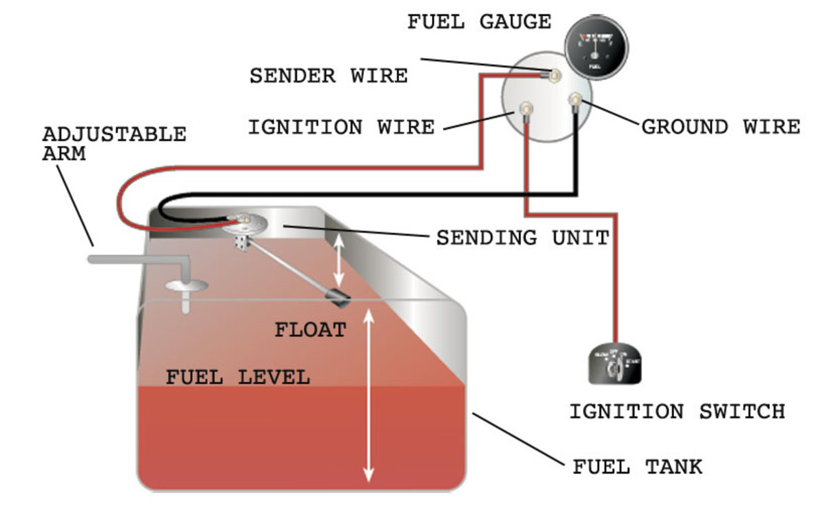
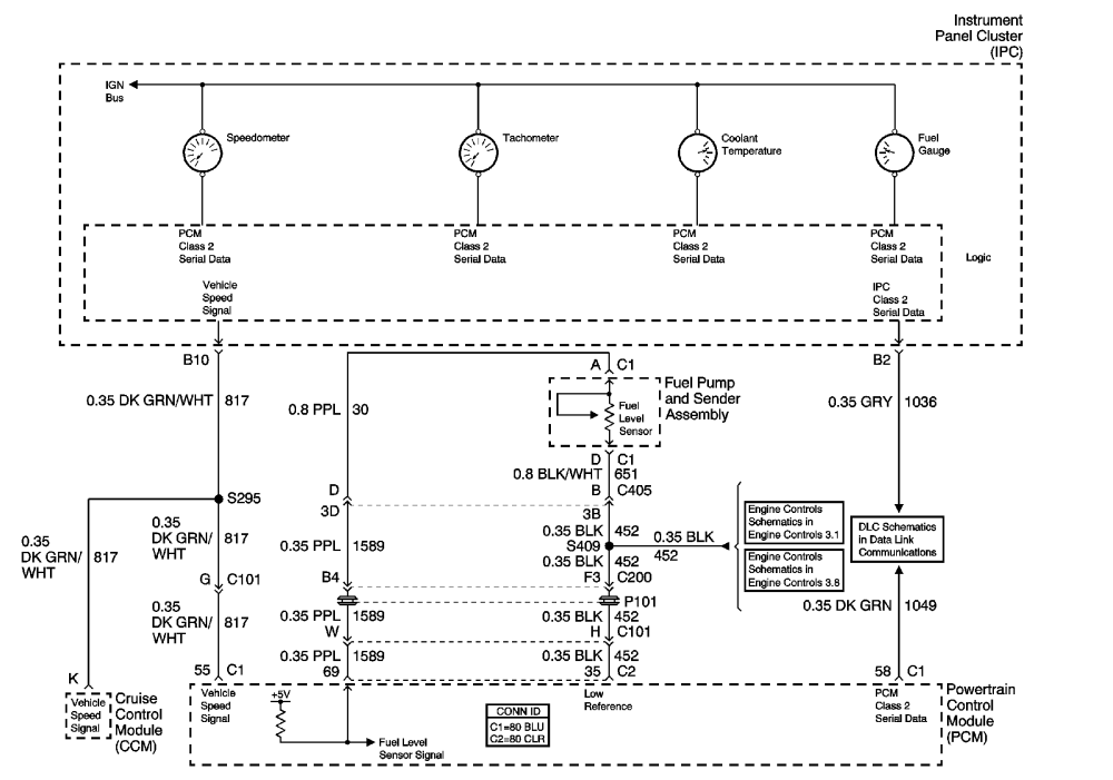
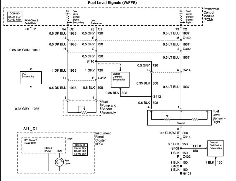
Sending unit wiring diagram. It shows the elements of the circuit as streamlined forms as well as the power as well as signal links between the devices. How to wire fuel gauge and sending unit complete explanation. Gm fuel sending unit wiring diagram. Column b shows the length from the underside.
Gm fuel sending unit wiring diagram. Super easy boat wiring and electrical diagrams. Figure 20 fuel tank sending unit removal and installation brilliant. How to test fuel sending unit and gas gauge chevelle gm duration.
There are two types of sending units. Using an ohm meter check the ohm readings with the sending unit out of the fuel tank. A wiring diagram is a simplified traditional photographic representation of an electrical circuit. Assortment of fuel gauge sending unit wiring diagram.
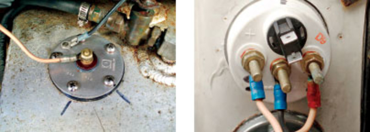
The older float style which uses a magnet embedded in a float that resides in a tube sending readings of how high in the tank it is floating and there is the newer style that measures electrical. If your gauge has color coded hook ups maintain this coding as you connect the sender and ground wires. Connect ground pink wire from the wema sending unit to a common grounding hook up connect black wire from the wema sending unit to gauge hook up. The fuel sending unit is responsible for what the fuel gauge on your vehicle reads.


