Simple Latching Circuit Diagram

Latch circuits can be either active high or active low.
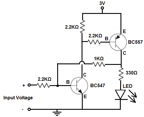
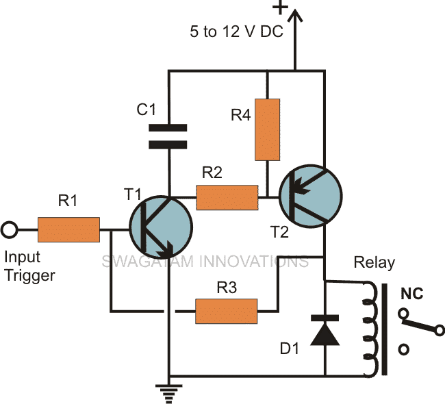
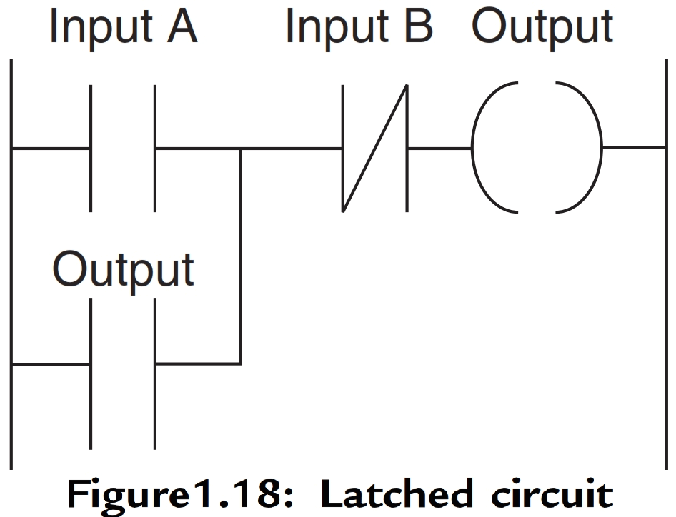
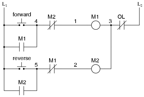
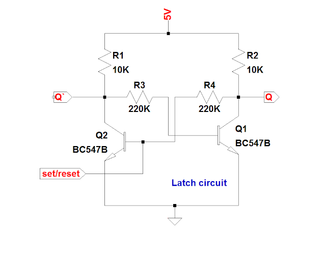
Simple latching circuit diagram. A latch circuit can be used to lock or latch the output of the circuit in response to an input signal and sustain the position even after the input signal is removed. The circuit has two buttons one is a push to make which closes when pressed but is otherwise open and the other is a push to break which opens when pressed but is otherwise closed. This is a simple latch circuit diagram project. A very common form of latch circuit is the simple start stop relay circuit used for motor controls whereby a pair of momentary contact pushbutton switches control the operation of an electric motor.
The difference is determined by whether the operation of the latch circuit is triggered by high or. Both inputs are normally tied to ground low and the latch is triggered by a momentary high signal on either of the inputs. A latch is an electronic logic circuit that has two inputs and one output. Both of these circuits use simple pushbutton switches to provide the trigger inputs.
The difference is determined by whether the operation of the latch circuit is triggered by high or low signals on the inputs. When the push to make button is pressed 12v goes across the coil energising the relay. The diagram above shows how such a relay can be used to make a latching relay circuit. One of the inputs is called the set input.
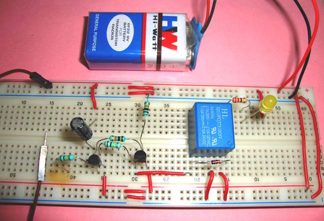
Electronic latch circuits can be either active high or active low. However you can easily imagine other sources for the trigger pulse. A latch circuit can be built by many ways for example it can be built by using transistors or ics latch circuits are used in electronic applications where the continuation of output is required whether the input signal goes off. Current limiting resistors must be used at the bases of bjt transistors otherwise they might burn.
In the active low circuit the resistors connect the gate inputs to 6 v and the switches short the gate inputs to ground. The output may be used to operate a load controlled through a relay scr triac or simply by the output transistor itself. The other is called the reset input. Circuit diagram of latching circuit is simple and can be easily built.
Electronics all in one for dummies.


