Simple Light Dimmer Diagram
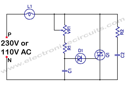
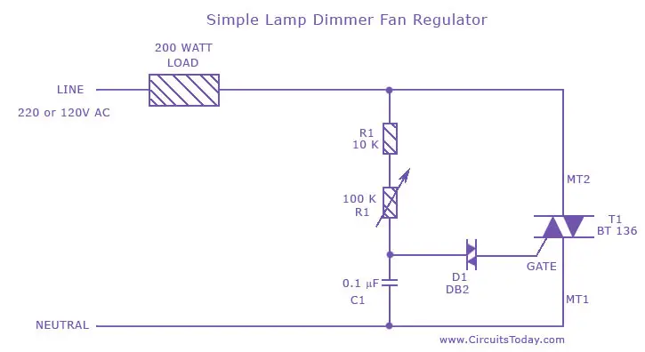
The light dimmer circuit or fan regulator circuit either case the circuit and design are the same only difference is the output load to be varied that is fan or light is used to control the brightness of the light or the speed of the fan according to our desire.
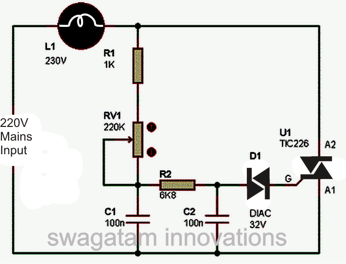
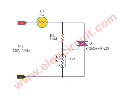
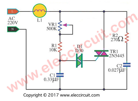
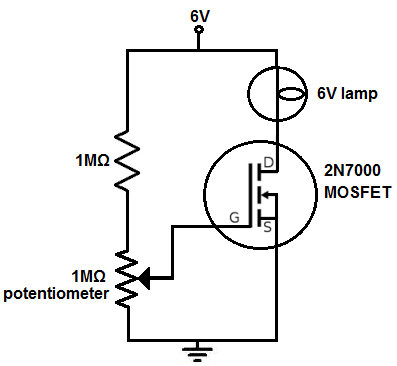
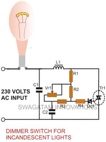
Simple light dimmer diagram. All we will use for this circuit is a mosfet which acts as an amplifier so that there is enough current to drive the light source. Simple light dimmer switch circuit the circuit diagram shown above is an classic example of a light dimmer switch where a triac has been utilized for controlling the intensity of light. When ac mains is fed to the above circuit as per the setting of the pot c2 charges fully after a particular delay providing the necessary firing voltage to. A light dimmer circuit is a circuit that is capable of dimming in or dimming out a light source.
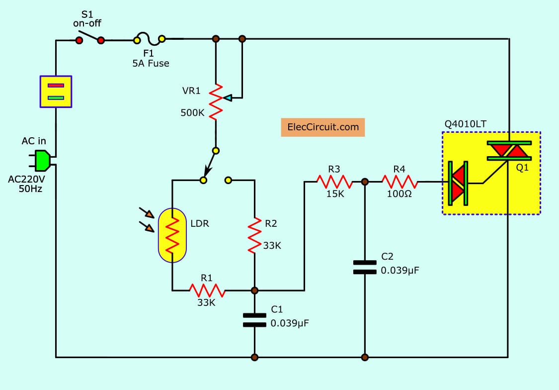
This easy electronic project is the simplest led dimmer that works well and uses minimum electronic components as possible the circuit consumes very low. This simple 220v light dimmer circuit can be used to adjust the brightness of mains lights. A rheostat or dimmer makes it possible to vary the current flowing to a light fixture thereby varying the intensity of the light. R1 10k r2 2k2 r3 180k potentiometer 250k.
Lamp dimmerfan regulator circuit we have modified this circuit. It uses a triac diac and has a radio frequency interference rfi noise suppression circuit built into it as well. The simplest led dimmer circuit diagram. The dimmer switch will have stranded wires that must be sliced to the solid cable wiring in a pigtail fashion.
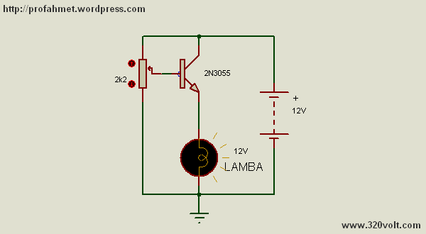
We are going to create as simple of a light dimmer as may be possible. And we use a potentiometer to the gate of the.


