Speed Controller Schematic

Dc Motor Controller Stuff To Buy In 2019 Circuit Diagram

Need Help With Pwm Motor Speed Controller Circuit
How To Build A High Torque Dc Motor Speed Controller Circuit

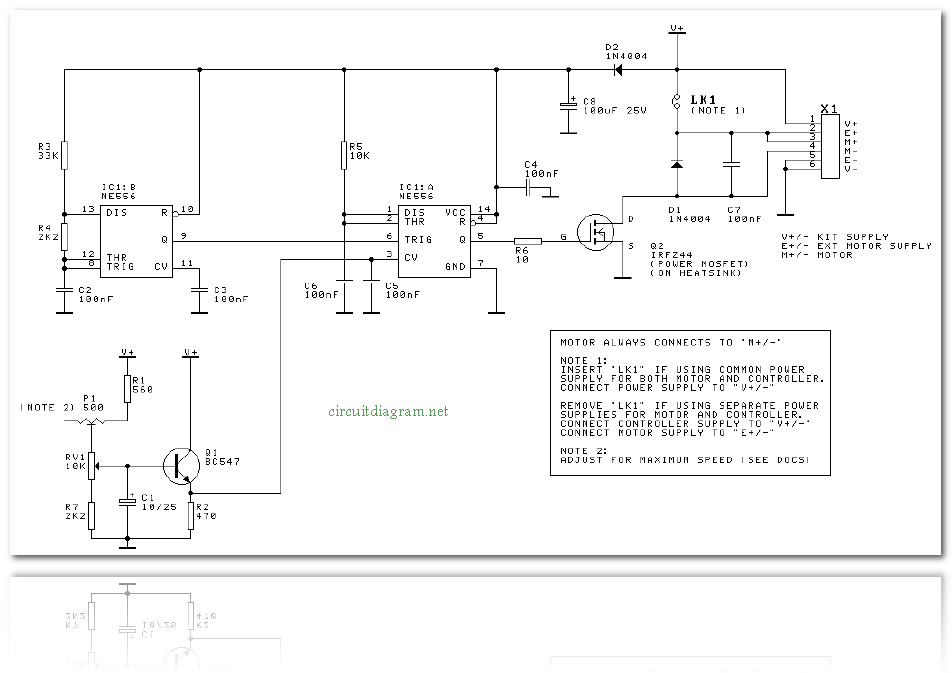
Complete circuit diagram for the motor controller along with the parts list has been included here.
Speed controller schematic. It may also provide reversing of the motor and dynamic braking. Consider a simple circuit as shown in figure below. An electronic speed control or esc is an electronic circuit that controls and regulates the speed of an electric motor. Full size electric vehicles also have systems to control the speed of their drive motors.
Miniature electronic speed controls are used in electrically powered radio controlled models. When it comes to controlling the speed of induction motors normally matrix converters are employed. Then check out this outstanding single chip pwm motor speed controller circuit that will give you a complete 360 degrees of continuously varying motor speed control right from zero to maximum. Ac motor speed control circuit.
How to make single phase motor speed control circuit. Based on your observations of these two diagrams explain how electromechanical relays are represented differently between ladder and schematic diagrams. The resulting pulse train has long positive and short negative pulse widths. Dc motor speed control circuit.
Ac motor speed control circuit. 3 phase induction motor speed controller. In this post we discuss the making of a simple 3 phase induction motor speed controller circuit which can be also applied for a single phase induction motor or literally for any type of ac motor. How to make single phase motor speed control circuit.
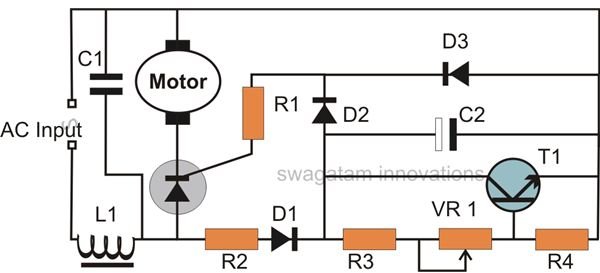
Interpret this ac motor control circuit diagram explaining the meaning of each symbol. Electronic speed controller circuit this technique works reasonably at full throttle as the battery is associated straight to the motor though at part throttle situations the flow of current through the resistor producing power to be lost in the form of heat. 220vac motor speed controller schematic for example when the motor of the drill machine is slowed down by the resistance of the drilled object the counter emf of the motor also decreases. The speed is controlled through an externally applied varying dc voltage source.
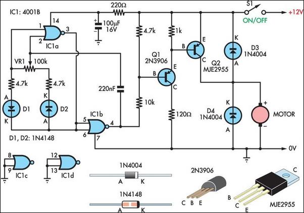
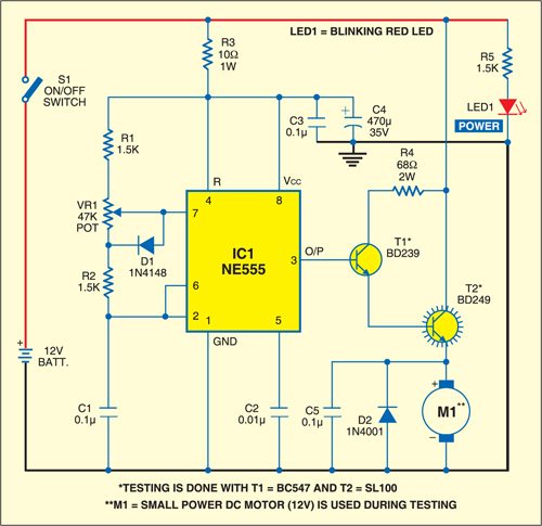
A circuit which enables a user to linearly control the speed of a connected motor by rotating an attached potentiometer is called a motor speed controller circuit. The dc motor speed control circuit is primarily a 555 ic based pwm pulse width modulation circuit developed to get variable voltage over constant voltage. The most striking feature of this circuit is its ability to provide full torque even at minimum motor speeds. On the other hand when the wiper arm of vr1 is at the bottom position c1 charges through r1 r2 and vr1 and discharges via r2.
Also explain the operation of this motor control circuit. If the button is pressed if the figure. Now the motor rotates at a high speed. The circuit incorporates a self stabilizing technique that maintains the speed of the motor even when it is loaded.
Therefore the motor speed is slow.

Ac Motor Speed Controller Circuit
Ac Motor Speed Controller
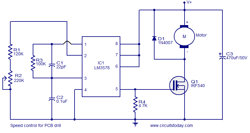
Speed Control For Pcb Drill Electronic Circuits And
Electronic Speed Controller
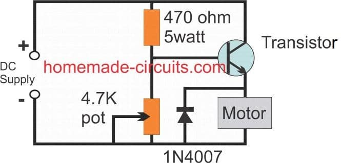
Two Basic Motor Speed Controllers Circuit Diagram

Dc Motor Speed Controller Pwm 0 100 Overcurrent Protection
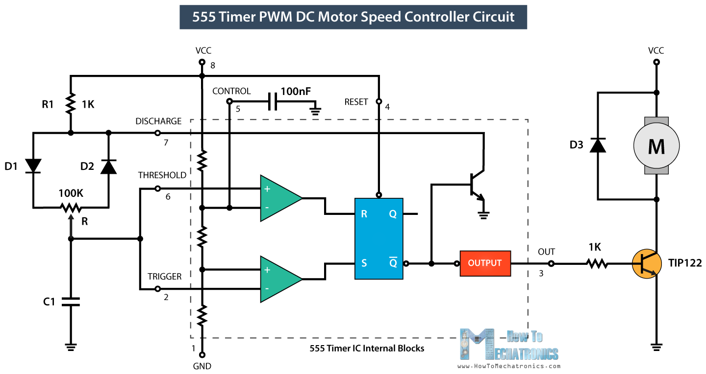
How To Make A Pwm Dc Motor Speed Controller Using The 555
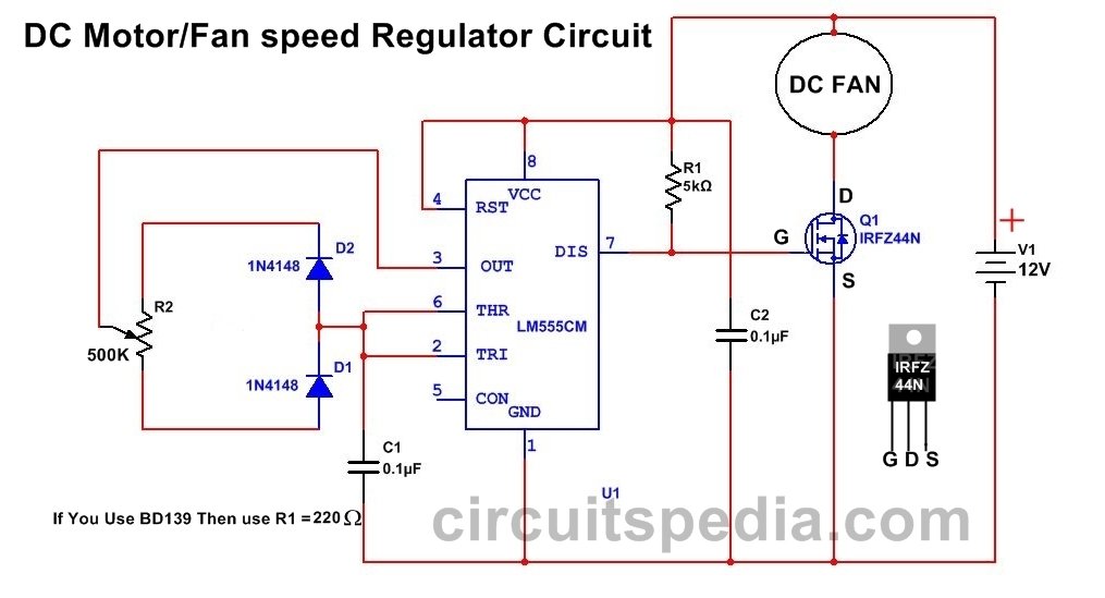
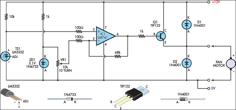
12v Dc Fan Motor Speed Controller Circuit Diagram Dc Fan

Pcb Drill Speed Controller

Mc 2100 Treadmill Motor Speed Control Circuit

Schematics Com Durable Electronic Speed Controller
Dc Motor Speed Controller Electronic Schematic Diagram
Junk Box Fan Speed Controller Circuit Diagram
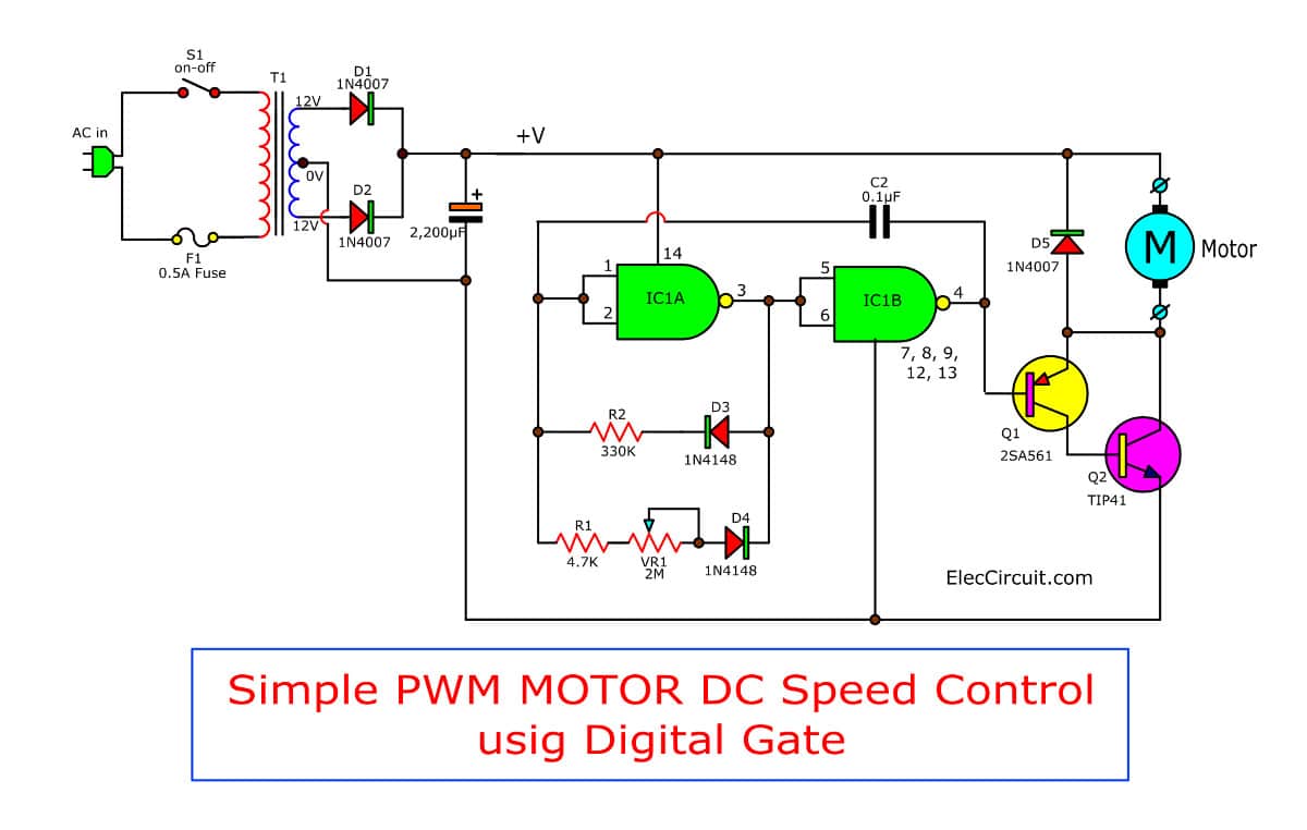
Simple Pwm Motor Control Circuit Using Ic 4011 Eleccircuit

Dc Motors And Stepper Motors Used As Actuators
3 Simple Dc Motor Speed Controller Circuits Explained
Dc Motor Speed Controller Detailed Circuit Diagram Available

Pin Em Free Electronics Circuits
