Trailer Lights Diagram 4 Pin

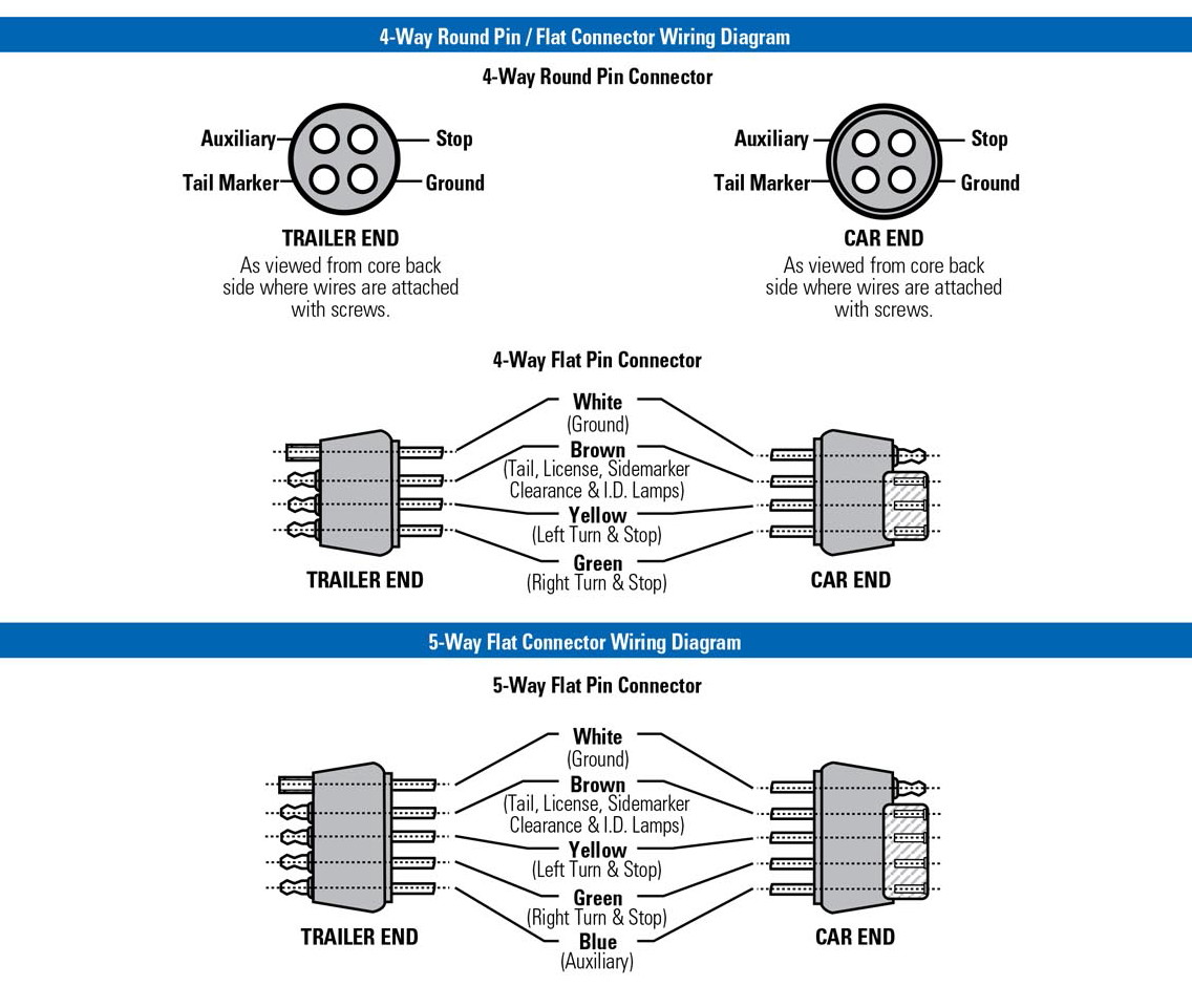
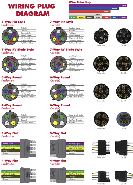
Please see the trailer wiring diagram and connector application chart below.
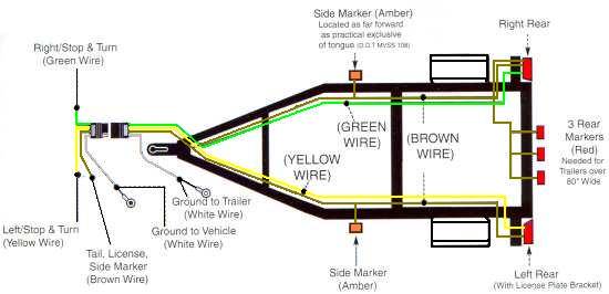
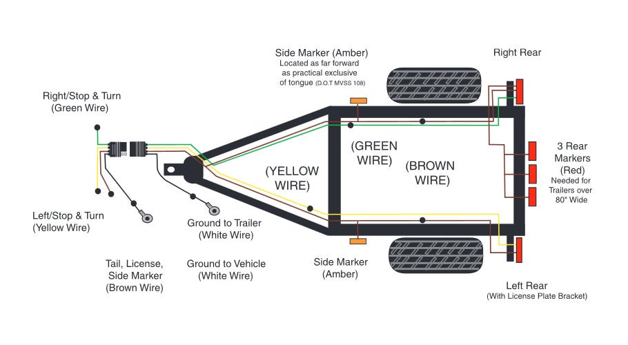
Trailer lights diagram 4 pin. Green right turn signal right brake light. Lighter duty trailer no brakes use a 4 pin connector. The 4 pin trailer uses yellow brown green and white wires. Below is the generic schematic of how the wiring goes.
The ground wire should be run from the frame of the vehicle to the trailer. Trailer electrical connectors come in a variety of shapes and sizes. Three wires are for the trailer while the last wire is the ground wire. Some of the lights were out but the light bulbs were fine.
By law trailer lighting must be connected into the tow vehicles wiring system to provide trailer running lights turn signals and brake lights. The rest you can ignore. 4 pin connectors are the standard used for most trailers. This type of connector is normally found on utvs atvs and trailers that do not have their own braking system.
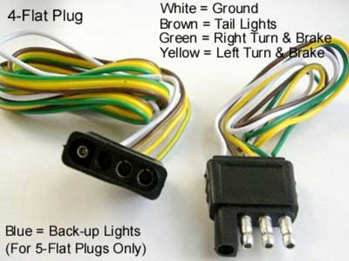
Trailer wiring diagrams 4 way systems. Installing the 4 pin trailer wires you will need to check the trailer manual for the correct wiring but typically the white wire is known as the ground wire while the brown for tail lights. 4 pin trailer wiring diagram. Rather than inspecting the old wires that were already corroded and falling apart i bought new 4 way trailer wiring and installed the electric myself.
Standard color code for wiring simple 4 wire trailer lighting question. The circuits are for left and right brake lights and running lights. Note that this type of 4 pin connector is less common that 4 pin flat connector. I have had to mess with trailer wiring for years once or twice a year anyway and i just cannot keep the color code right ect whiteground brn running lights grn right turn yellow left turn.
4 way flat molded connectors allow basic hookup for three lighting functions. Many trailers have three circuits. Above we have describes the main types of trailer wiring diagrams. The 4 pin connector only has the first 4 items listed.

