Typical Motor Wiring Diagram
Basic Wiring For Motor Control Technical Data Guide Eep
Basic Wiring For Motor Control Technical Data Guide Eep

Motor Control Design Automationprimer
When diagnosing a faulty automotive motor it is often impossible not to perform major disassembly such as the fuel pump itself.
Typical motor wiring diagram. They show the relative location of the components. Wiring diagrams vs line diagrams most of the diagrams in this book are shown in two ways. The power cables will be run to your new wire marine custom marine switch panel and your tinned marine negative bus bar. Prevent voltage drop by using larger cable.
Three phase motor power control wiring diagrams 3 phase motor power control wiring diagrams three phase motor connection schematic power and control. Figure 1 typical wiring diagram. Involved in motor control circuit wiring understanding how it works becomes easier and less intimidating. Figure 1 is a typical wiring diagram for a three phase magnetic motor starter.
Always use wiring diagram supplied on motor nameplate. Its very common to find different styles of schematics combined in a single wiring diagram. The typical starting system wiring diagrams can divide into non relay control type single starter relay control type and security starter relay control type. The top part of.
Basic wiring for motor control technical data. They can be used as a guide when wiring the controller. Keep in mind that the longer your wiring run from the battery to switch panel is the more voltage drop youll have more about voltage drop. On these wiring diagrams draftor motor line voltage stats thermostats wsubbase wired motor contactor motor starter 3 phase supply voltage all others specials c1313p see figure 1.
Three phase wiring diagrams always use wiring diagram supplied on motor nameplate. Learn the procedures thatll save time during the diagnostic process. Typical wiring diagram manual indoor gas fired unit heaters and duct furnaces standard natural vent or power vented. The specific circuit needs to be respectively learned referring to different typical control circuits.
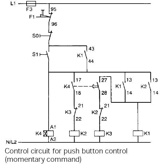
Typical wiring diagrams for push button control stations 3 genera information at each circuit is illustrated with a control circuit continued schematic or line diagram and a control station wiring diagram.

Typical Wire Diagram Of Drum Control Ac Wound Rotor Motor

Typical Wiring Diagram For Drum Controller Operation Of A C

Typical Connection Diagrams Three Phase Motors Y Start

Typical Wiring Diagram For Drum Controller Operation Of A C Wound Rotor Motor And Starters
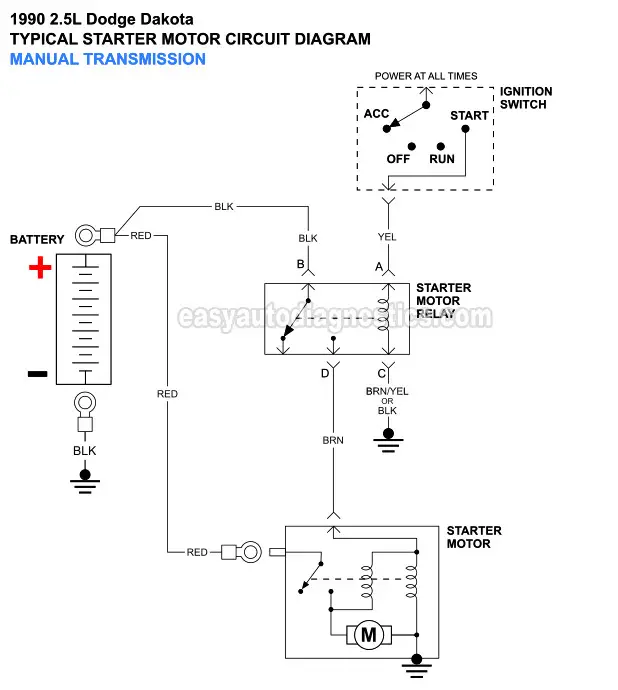
Part 1 Starter Motor Wiring Diagram 1990 1993 2 5l Dodge
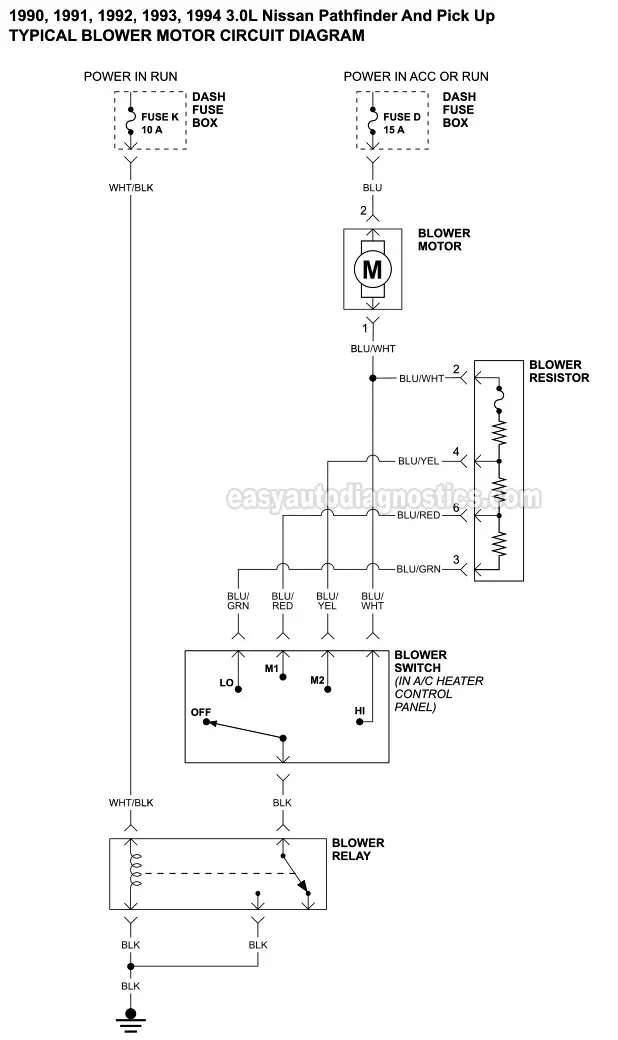
Part 1 Blower Motor Circuit Diagram 1990 1995 Nissan
Starting Motor Wiring Diagram Wiring Schematic Diagram

Smc Motor Wiring Diagram Wiring Schematic Diagram

Typical Wiring For The Pro Dno Vtx And Ncc Controllers

Drum Controller Wiring Diagram Wiring Diagram
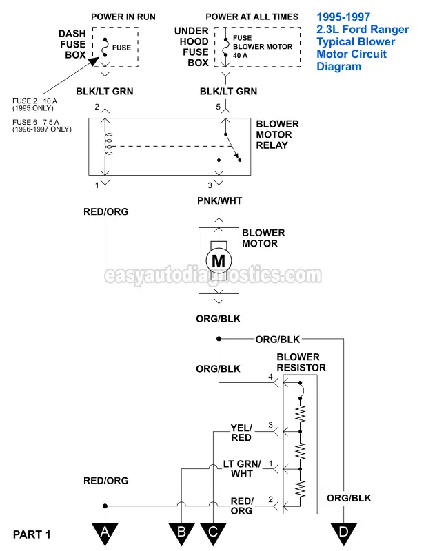
Part 1 Blower Motor Circuit Diagram 1995 1997 2 3l Ford
Typical Circuit Diagram Of Star Delta Starter Plc Plc

Wrg 4838 Typical Motor Wiring Diagrams

Dol Panel Diagram Wiring Library

Ladder Diagram Basics 3 2 Wire 3 Wire Motor Control Circuit

Starting Motor Wiring Diagram Wiring Schematic Diagram
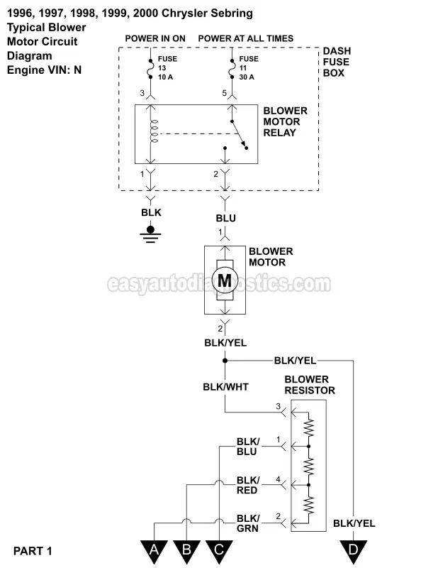
Blower Motor Wiring Diagram 1996 2000 2 5l V6 Sebring And

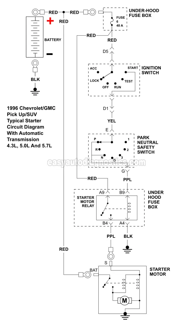
Part 1 Starter Motor Circuit Wiring Diagram 1995 1 5l
