Wiring Diagram For Led Light Bar

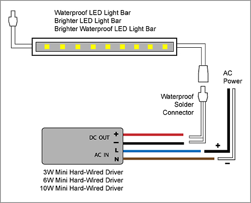
It reveals the elements of the circuit as streamlined forms and also the power and also signal connections between the tools.
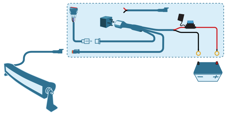
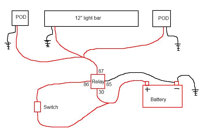
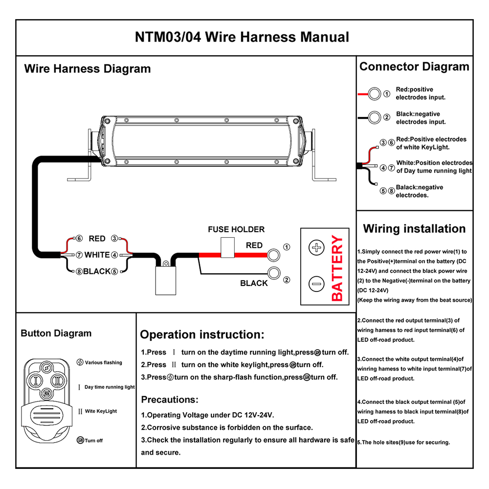
Wiring diagram for led light bar. Collection of wiring diagram for led light bar. Httpsamznto33rf4mq used in this video auxbeam led light bar wiring harness. Learn how to wire a relay for off road led light bars and work lights. Now youre on to your last step reconnect the negative terminal to your battery and you should be.
Light bar part s 76204 7620876212 76220762317623876246 led. Learn what a relay is how it works and why you should use one. Httpsamznto2b41h1x used in this video auxbeam 22 straight led light. This is your guide on how to install a universal relay harness wiring set with an onoff switch.
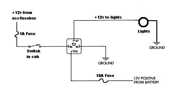
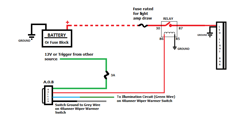
The terminals have a standard numbering scheme. When wiring led light bar relays or switches. If drilling through firewall be sure to use some kind of grommet so the wires do not rub wire loom a. Be sure the relay power capacity exceeds the amperage of your light bars maximum current draw.
How to install offroad led light bar w relay switch. Light bar wiring kit part 76200 3. Auxbeam 32 curved led light bar. Step 11 reconnecting the negative terminal.
The diagram below shows the bottom side of a standard 12vdc automotive relay. A wiring diagram is a streamlined standard photographic depiction of an electric circuit. If you are wiring up spot lights connect a plug to each light. For this guide w.
This wiring kit will work with any led light product such as the ford f 150 led light bar and makes them easy and safe to work with. I had problems with it and its known to give problems so by wiring the led light bar with this signal if the dimmer relay goes off i still have the led bar to light up my way. Wiring an led light bar. A fused wire runs between the positive battery terminal to relay.
Route the harness from the mounted switch to the battery and to the led light bar. So the wire with high beam signal to trigger the led bar relay is wired inside the cabin from the connector in the steering column to the button and form there to the. A wiring diagram is a simplified standard photographic representation of an electric circuit.

