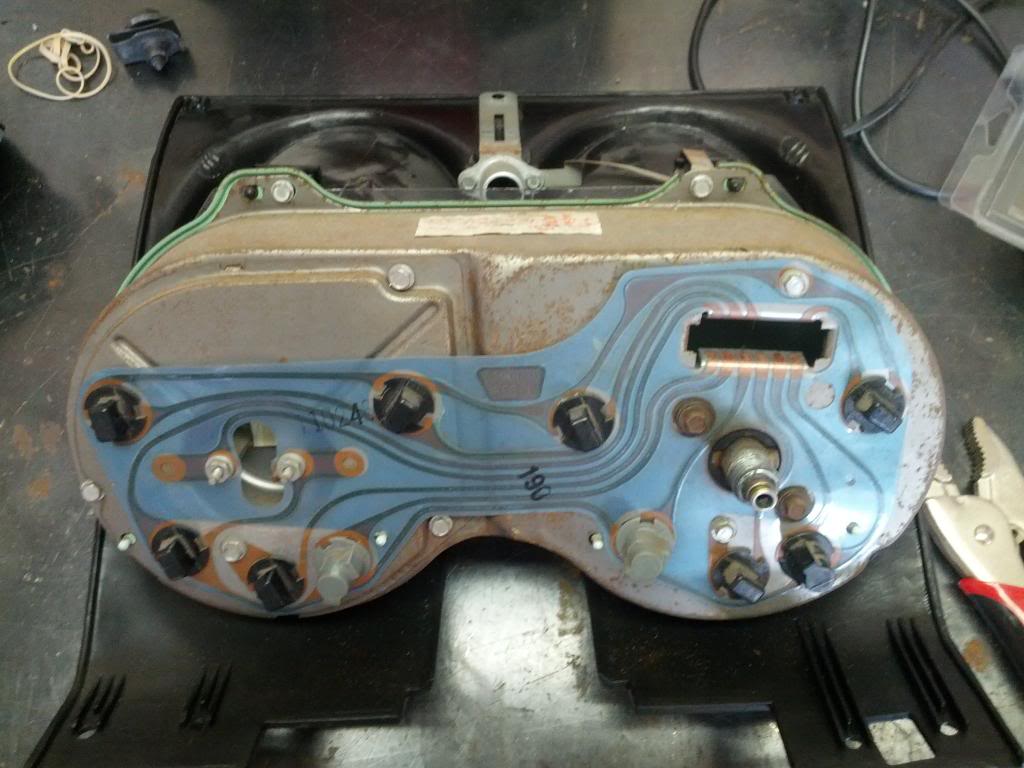
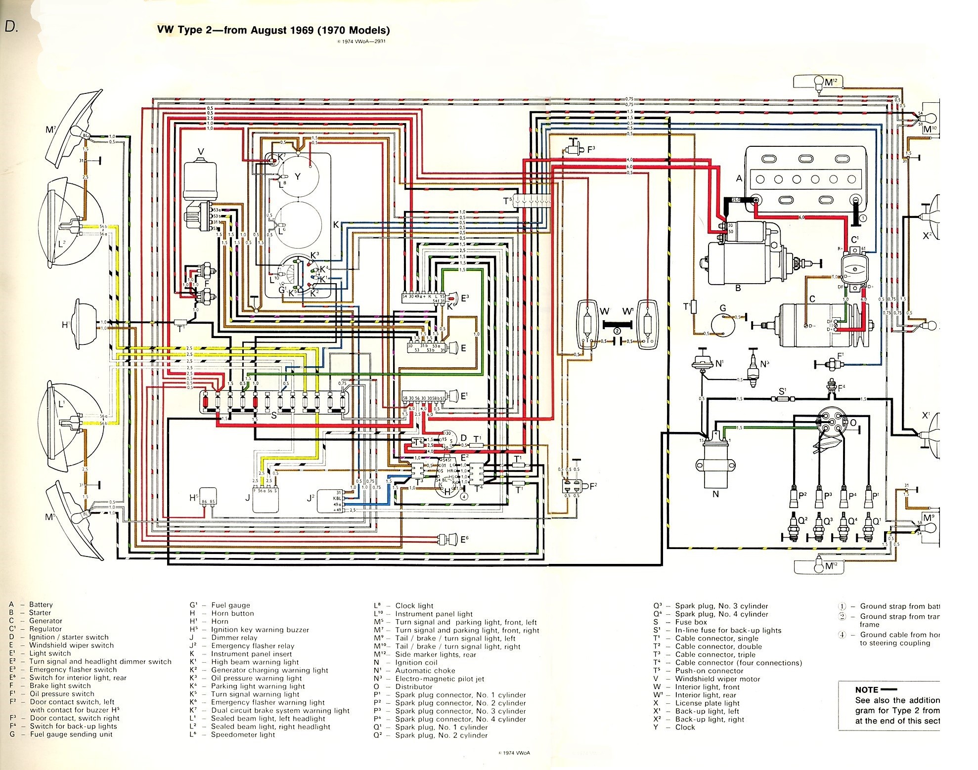
1967 Camaro Fuel Gauge Wiring Diagram

Sample diagram how to read and interpret wiring.
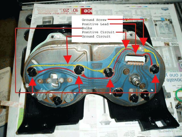
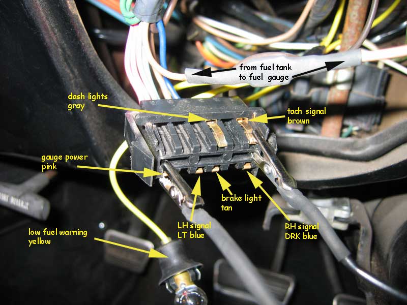
1967 camaro fuel gauge wiring diagram. The 1967 low fuel module. The module plugs into the fuel gauge for power signal and ground. Fuel gauge troubleshooting begins with isolating the problem either to the gauge sending unit fuse or wiring. Engine controls wiring schematic 1967 71 models.
How does the 1967 69 camaro low fuel indicator work. If not you have a wiring problem or a bad gauge. General motors fuel gauge troubleshooting. 76 best of 1967 camaro wiring diagram pdf pictures welcome for you to my personal website in this occasion well provide you with about 1967 camaro wiring diagram pdfnow this is the primary picture.
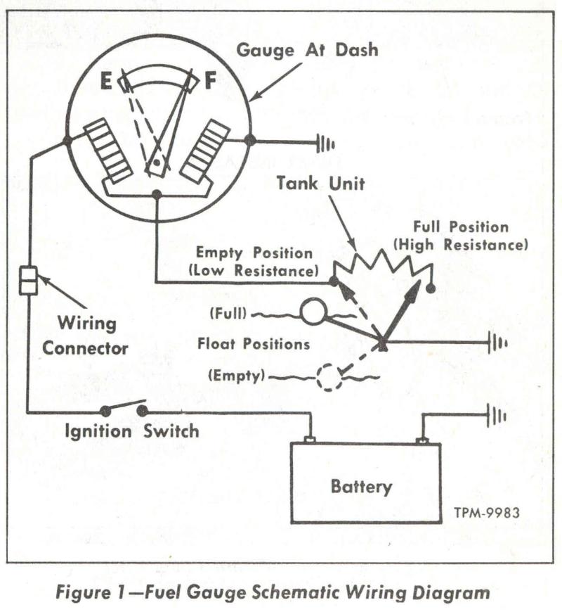
Common wiring diagram symbols. To diagnose the fuel gauge here is what i would do. End the mystery today by purchasing this inexpensive wiring diagram from ricks first generation. 1 a break in the wire from the gauge to the sending unit 2 a bad sending unit 3 a bad ground at the sending unit or 4 the gauge itself is bad.
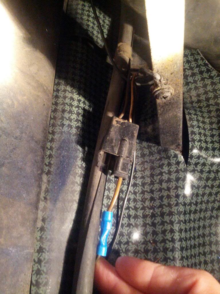
Correct tan wire to sending unit black wire to ground a screw at the tank rib on the pass side. Autozone repair guide for your chassis electrical wiring diagrams wiring diagrams. If the tank harness is disconnected and a 100 ohm resistor is attached between the tan wire of body harness at the tank or at the drvr kick panelrocker panel to ground the gauge should indicate a full tank. 1967 68 fuel tank sending unit harness.
The possible causes for the malfunctioning gauges are. The most common gauge problems are either a bad ground at the tank or a sender problem. 1967 rally sport and console gauge schematics are not included in this manual. Touch the tan wire from the body to any convenient ground and the gauge should read empty.
The 38 inch fitting is 68 and newer. 1967 camaro wiring diagram davehaynes from 1967 camaro wiring diagram pdf sourcedavehaynesme. Gm camaro 1967 1981 repair guide. The sn76 connect the red wire of the sn76 to the pink wire on the powerlighting connector position h connect the black wire of the sn76 to the black wire on the powerlighting connector position j and connect the yellow wire of the sn76 to the white wire on the signal connector position j.
Those schematics are sold separately under part gwm 79. If the fuel gauge responds correctly the fuel gauge and sending unit wire at this point are. See figure d below for a sn76 wiring diagram. With the tan wire disconnected at the fuel tank the fuel gauge should read past full with the ignition on.
Cfg center fuel gauge. There is a fourth yellow wire that comes from the module that goes to the dash through the console harness and the dash harness console extension to activate a light in the instrument cluster.
