Control System Block Diagram
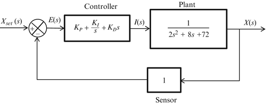
By using block diagrams when examining larger systems attention can be focused on a smaller number of elements or subsystems whose properties may already be knownby doing this a set of individual blocks representing the various elements or subsystems is formed and these blocks are interconnected to represent the whole system.
Control system block diagram. Basic elements of block diagram. Block diagram in contol system. The basic elements of a block diagram are a block the summing point and the take off point. However these methods do not work for complicated systems.
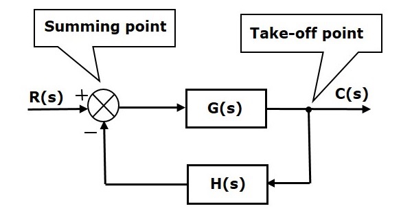
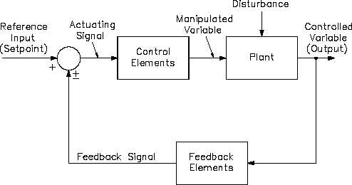
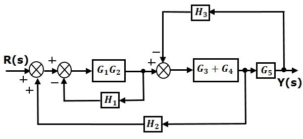
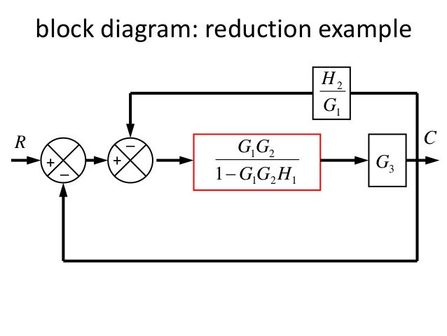
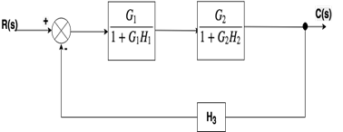
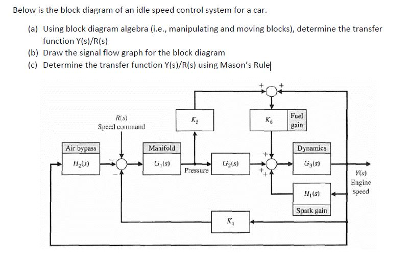
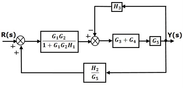
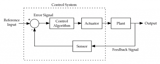
Block diagrams can be systematically. Let us consider the block diagram of a closed loop control system as shown in the following figure to identify these elements. It is easier and better to derive transfer function of control element connected to the system separately. Block diagram in control systems.
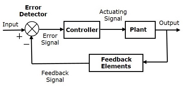
From wikibooks open books for an open world. Any system can be described by a set of differential equations or it can be represented by the schematic diagram that contains all the components and their connections. In other words practical representation of a control system is its block diagram. A block looks on paper exactly what it means.
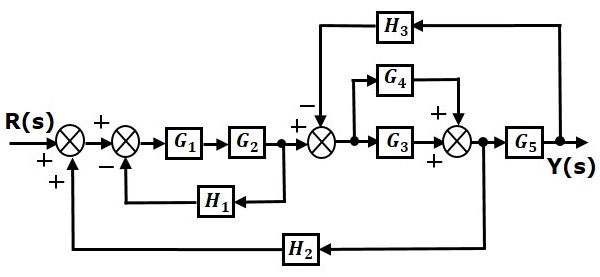
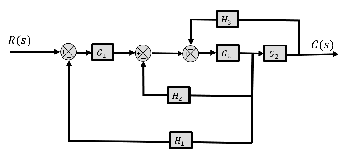
Hello friends in this blog article we will learn block diagram algebra in the control system. Block diagrams are a useful and simple method for analyzing a system graphically. Gscsrs where rs laplace transform of the input variable. It is not always convenient to derive the entire transfer function of a complex control system in a single function.
We know that the input output behavior of a linear system is given by its transfer function.
