Mercruiser Trim Wiring Diagram

Mercruiser Trim Solenoid Wiring Diagram Yahoo Image Search
Mercruiser Power Trim Wiring Schematic Perfprotech Com

Question Is What Colors Are The Wires To The Up Trim
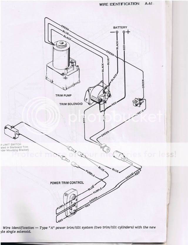
Figure 2 is a functional diagram of the hydraulic.
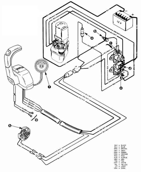
Mercruiser trim wiring diagram. It will fit all mercruiser 1 drives made from 1975 to date including alpha one gen ii and bravo. Put simply it has you trim the stern drive all the way up answer yes then trim it all the way down and answer yes again. Some models may differ. Each component ought to be set and connected with different parts in particular way.
I presume this teaches the system the range of trip and it simply interpolates any percentage of trim and indicates it on the needle. Tilt and trim switch wiring diagram best trim and hydraulics need. Some models may also be equipped with a trim indicator sender. Injunction of two wires is usually indicated by black dot to the intersection of two lines.
Otherwise the arrangement will not work as it ought to be. Click here for adjustment and replacement procedures sierra switches. Theres a calibration menu in the tachometermulti function display. According to earlier the traces at a mercruiser trim sender wiring diagram signifies wires.
Sometimes the wires will cross. This replaces mercruiser pn 805320a1. Click here for prices. Or handle a pump motor and a trim limit switch with connecting wiring.
Power trim and tilt systems the mercruiser power trim system permits. However it doesnt imply link between the cables. Mercury trim motor wiring diagram download collections of mercruiser trim solenoid wiring diagram yahoo image search results. Galericanna wp content 2018 07 mercury.
Mercruiser 43 wiring diagram 1989 mercruiser 43 wiring diagram 1996 mercruiser 43 wiring diagram mercruiser 43 alternator wiring diagram every electric structure is made up of various different components.
Wiring Diagram For Motor Trim Solenoid Page 1 Iboats
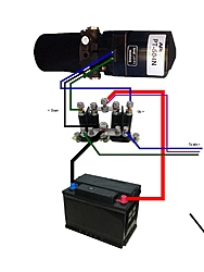
Single Solenoid Trim Pump Wiring Page 1 Iboats Boating

Electrical Wiring Mercury Outboard Trim Gauge Wiring
Single Solenoid Trim Pump Wiring Page 1 Iboats Boating
Mercury Trim Pump Wiring Diagram Is This Right
Power Trim Wiring Diagram I Just Purchased A Mercury Black

Mercury Outboard Trim Switch Wiring Diagram Electrical Gauge

Mercury Outboard Trim Switch Wiring Diagram Electrical Gauge

Troubleshooting Testing And Bypassing Spdt Power Trim Tilt

Mercruiser Trim Switch Wiring Diagram Limit Mercury Outboard

I Have A 150 Hp 1983 Mercury Blackmax It Has The External

Mercury Outboard Trim Switch Wiring Diagram Electrical Gauge

Tilt Trim Motor Tips Arco

I Need A Wiring And Hydraulic Line Diagram For A 1976

Yamaha Outboard Power Trim Tilt Relay Wiring Diagram

Oildyne Trim Pump Wiring Diagram Wiring Schematic Diagram

Mercruiser Trim Wiring Diagram Wiring Library

Mercruiser Tilt Trim Gauge Wiring Diagram Catalogue Of Schemas
