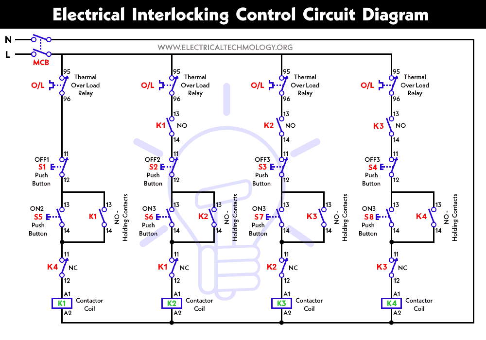
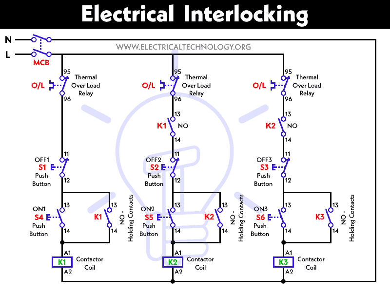
Interlock Forward Reverse Motor Control Diagram
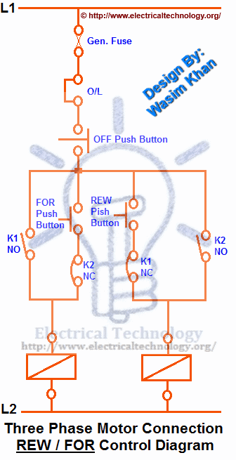
Three phase motor power control diagrams.
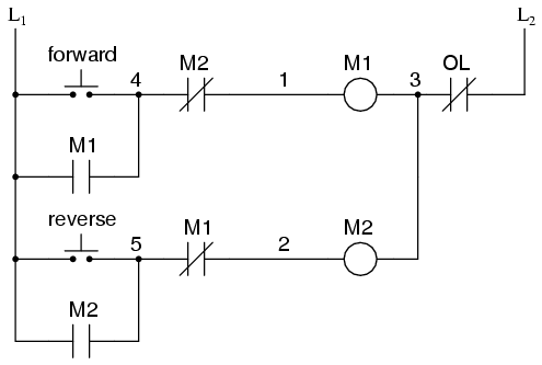
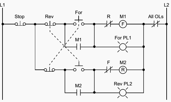
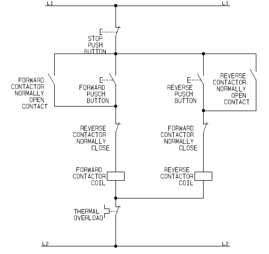
Interlock forward reverse motor control diagram. Figure 1 illustrates a hardwired forwardreverse motor circuit with electrical and push buttoninterlockingsfigure 2 shows the simplified wiring diagram for this motor. Figure 1 illustrates a hardwired forwardreverse motor circuit with electrical and push button interlockings. Three phase motor contactor auxiliary contact interlock swit circuit. Now if you have any question and have any suggestion then you can use the below comments box.
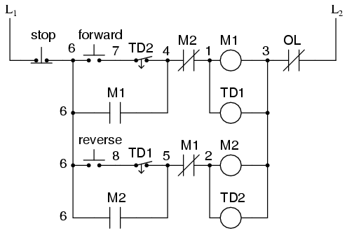
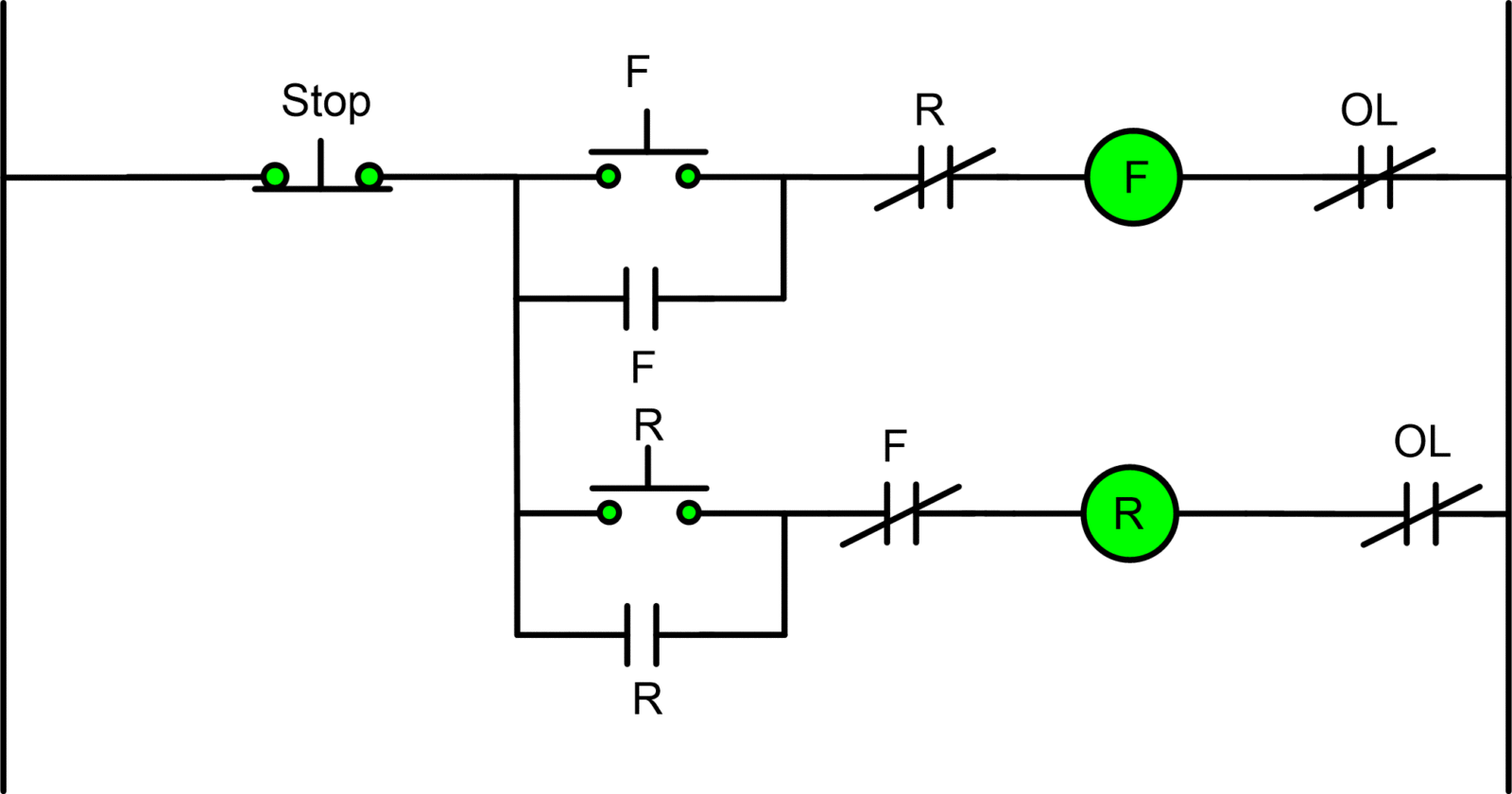
Draw the power circuit control circuit and ladder logic diagram for a three phase induction motor forward reverse control and explain the operation drawing of interlocked forward reverse contactors electrical schematic for rotation inversing contactors for three phase electrical motors. I hope the above forward reverse motor control diagram 3 phase motor forward reverse starter wiring diagram help you to understand this connection. Name 3ph forward reverse jpg views 31507 size 15 4 kb circuit diagram for delta state forward reverse motor control diagram dual motor starter wiring diagram inspirationa electric 220v 3 wires schematic. We could replace the push button switches with toggle.
The interlock contacts installed in the previous sections motor control circuit work fine but the motor will run only as long as each push button switch is held down. Three phase induction motors runs with two speeds 1 direction and two speeds two directions motor control and induction motors reverse forward operation is the types of electrical interlocking. A how to guide for the control circuit of a forward reverse electric motor controller. I hope you will share this post on social media.
The plc implementation of this circuit should include the use of the overload contacts to monitor the occurrence of an overload condition. Single phase reversing motor starter wiring diagram solutions. Homecontrol electrical interlocking power control diagram.

