Wiring Diagram Of Ceiling Fan
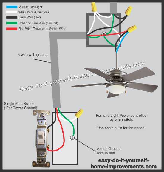
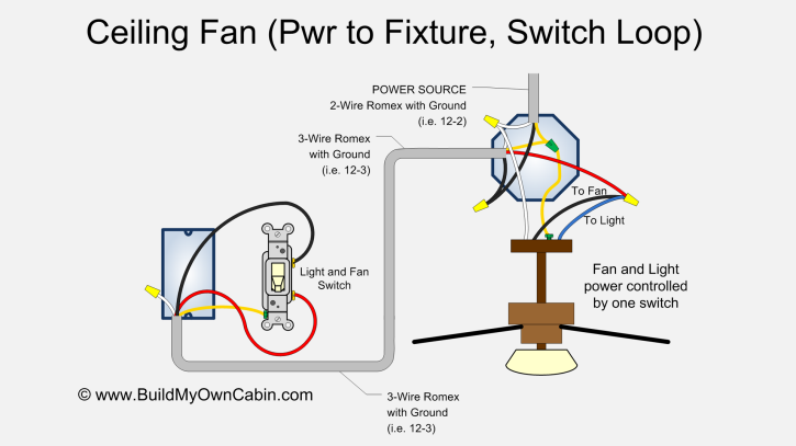
Wiring diagram 1 power enters at the wall switch box.
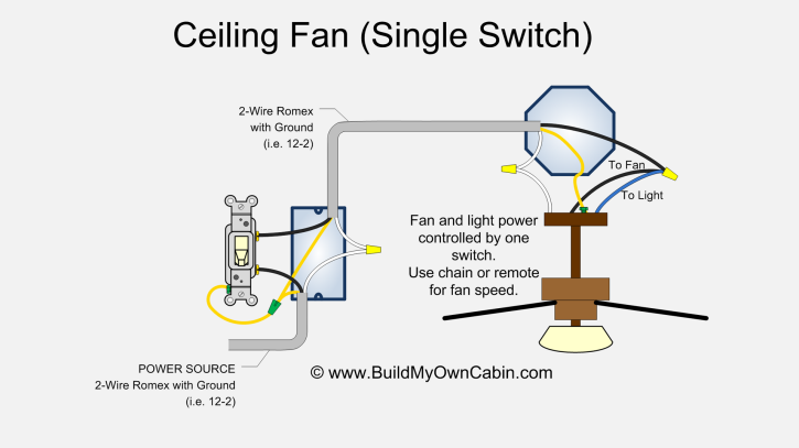
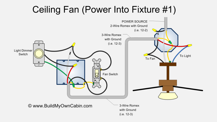
Wiring diagram of ceiling fan. This wiring diagram shows the power starting at the ceiling fan box. Installing a ceiling fan. Need step by step instructions on replacing ceiling fan. Line voltage enters the switch outlet box and the line wire connects to each switch.
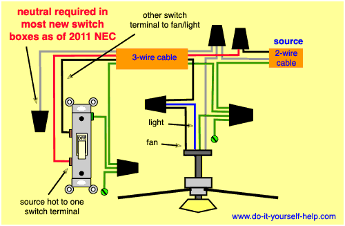
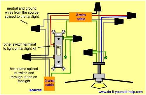
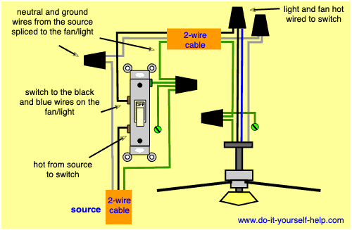
Ceiling fan switch wiring diagram 2. Speed switch connection table. These diagrams to follow are based on the ceiling fan wires having a color code of. The source is at the switches and the input of each is spliced to the black source wire with a wire nut.
This might seem intimidating but it does not have to be. Take a closer look at a ceiling fan wiring diagram. Collection of 4 wire ceiling fan switch wiring diagram. Speed switch connection table.
It reveals the elements of the circuit as simplified shapes and the power and signal connections between the tools. Black speed switch with only three terminals connected two wire capacitor. The power source is extended so that is can supply power down to the switch box. Ceiling fan with light kit wiring diagram.
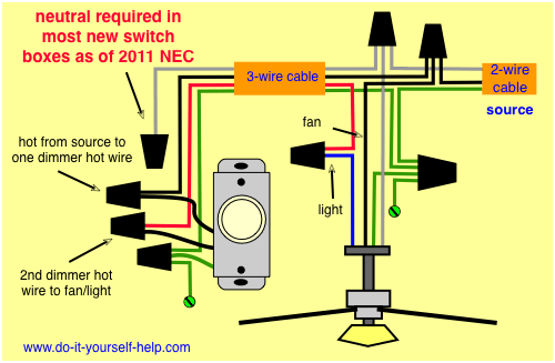
This wiring diagram illustrates the connections for a ceiling fan and light with two switches a speed controller for the fan and a dimmer for the lights. Ceiling fan wiring diagram 2. Household circuits usually consist of a black wire a white wire and a bare copper ground wire. The fan control switch usually connects to the black wire and the light kit switch to the red wire of the 3 way cable.
With these diagrams below it will take the guess work out. Wiring a ceiling fan when the power enters at the ceiling fan box. Do not use an electronic speed control on this type of fan. Black speed switch three wire capacitor.
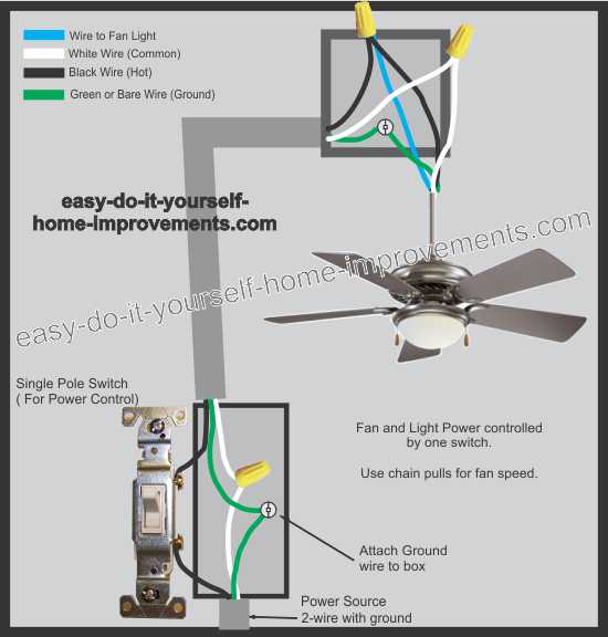
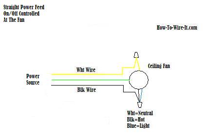
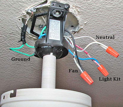
White neutral black fan blue light green ground some manufacturers may use different color codes so be sure to follow the instructions that come with your particular product. Ceiling fan wiring diagram 1. Switched lines and neutral connect to a 3 wire cable that travels to the lightfan outlet box in the ceiling. Power starting at the switch box this wiring diagram shows the power starting at the switch box where a splice is made with the hot line which passes the power to both switches and up to the ceiling fan and light.
This is a simple illustrated circuit diagram of ceiling fanto be noted that the wiring diagram is for ac 220v single phase line with single phase ceiling fan motor. A wiring diagram is a streamlined standard pictorial depiction of an electrical circuit. This can create some confusion when it comes to which wires to connect together. Here a simple spst switch is used to supply power or not to the fan motor and a regulator is used to controlling the fan speed.
Ceiling fans have different colored wires coming from the motor that dont quite match the household circuit wires colors.
