Xlr Wiring Diagram 4 Wire

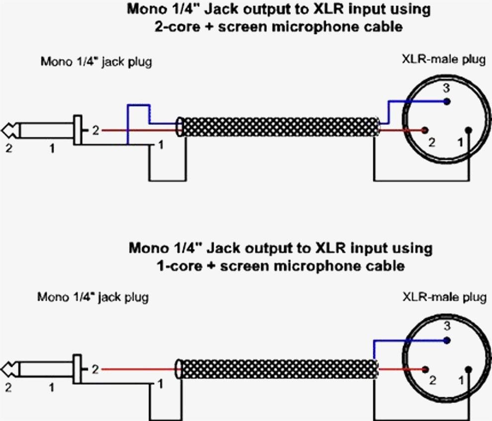
The most comon way to wire a 3 pin xlr to a 14 inch 65mm mono plug sometimes called a jack plug is to join the negative and shield together.
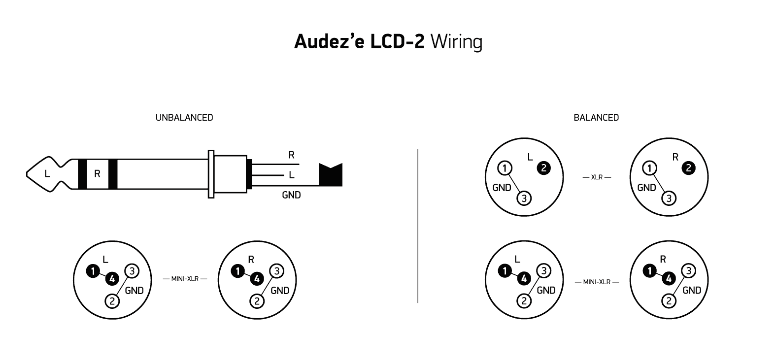
Xlr wiring diagram 4 wire. As well as speakon to 1 4 wiring diagram in addition neutrik xlr wiring diagram as well as input output wiring diagram along with midi connection diagram in addition neutrik xlr wiring diagram together with xlr wiring guide along with. Starquad wiring for balanced xlr to xlr connections. How to wire an xlr a 1 4 jack rh media mono wiring wiring an xlr 1 4 jack bo wall box to a single cable neutrik ncj6fi s xlr to mono jack xlr wiring diagram 4 wire rh 20 zeevissendewatergeus nl microphone diagrams 1 xlr to 1 4 wiring diagram xlr 1 4 mic read more. This wiring configuration gives you a balanced mono audio cable.
On the four pin amphenol pin 2 is a high impedance unbalanced output. The following is the aes industry standard for balanced audio xlr wiring commonly known as pin 2 hot. Xlr 4 pin wiring diagram thanks for visiting our site this is images about xlr 4 pin wiring diagram posted by maria nieto in xlr category on oct 18 2019. A wiring diagram is a streamlined conventional photographic depiction of an electric circuit.
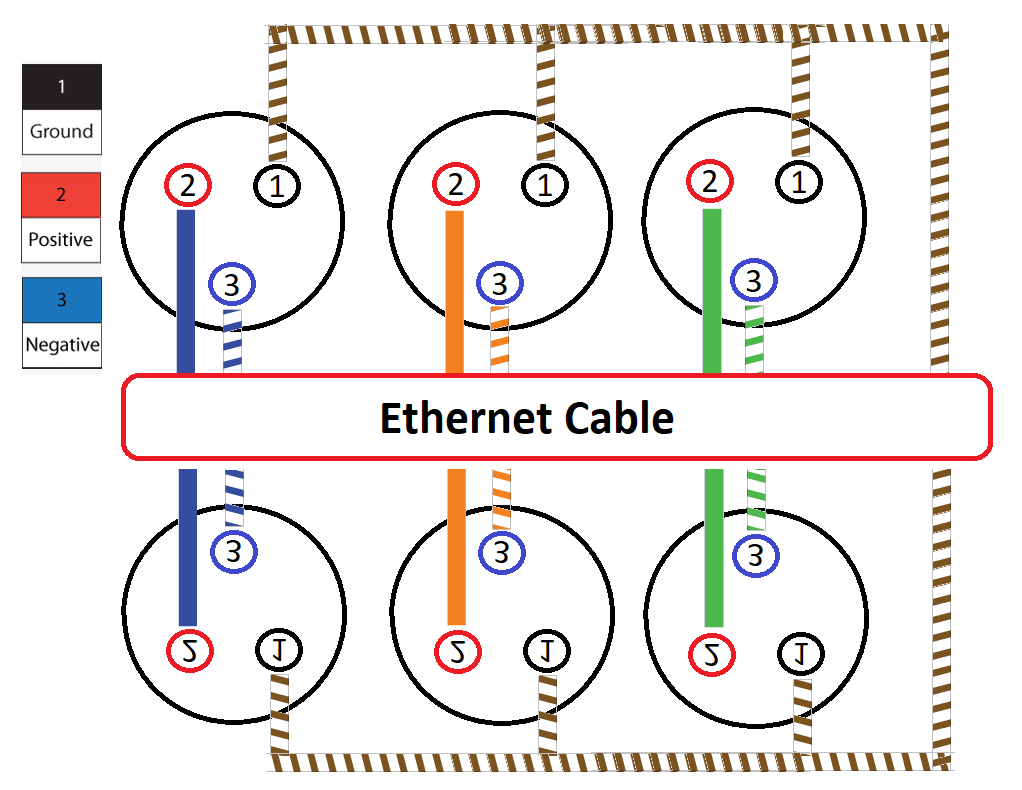
Xlr 4 pin wiring diagram may 05 2019 horbar. To properly wire a balanced to balanced cable using 4 conductor starquad and maximise noise rejection opposing conductors are terminated together into an xlr 3 connector or terminal block. Collection of xlr to mono jack wiring diagram. Or buy pre made cables for vintage shure mics from.
Tutorial how to wire 2 amps into your pa setup without using an active crossoverp h aac duration. Some manufacturers especially in vintage equipment do not follow this standard and instead reverse the polarity of pin 2 and 3. You can also find other images like images wiring diagram images parts diagram images replacement parts images electrical diagram images repair manuals images engine diagram images engine scheme diagram images wiring harness diagram. 3 pin xlr audio pinout.
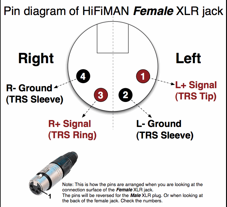
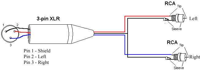
3 pin xlr connectors are standard amongst line level and mic level audio applications. The above diagram shows you the pin numbering for both male and female xlr connectors from the front and the rear view. Bias return 20 k ohm resistor to ground or equivalent active bias management circuit jumpered to pin 3 when used with most condenser microphones pin 4. The rear view is the end you solder from here are the connections on each pin.
This can be done by either soldering the shield and negative wires of the xlr to the sleeve of the plug. Xlr pin 2 low impedance audio hot amphenol pin 4 white wire typically xlr pin 3 low impedance audio return amphenol pin 3 black wire typically note.


