Motor Contactor Wiring Diagram

How to wire a contactor and motor protection switch.
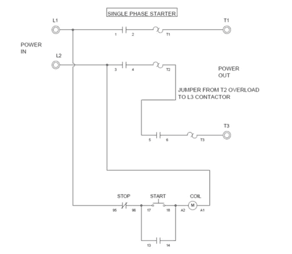
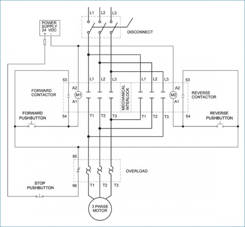
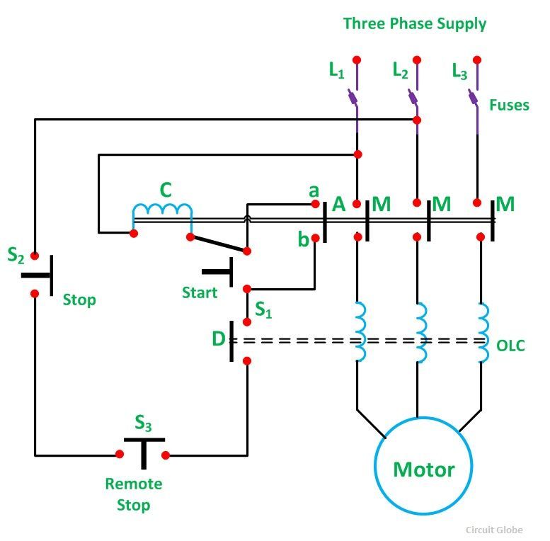
Motor contactor wiring diagram. Its is important to. It uses two contactors two auxiliary contact blocks an overload relay a mechanical interlock two normally open start pushbuttons a normally closed stop pushbutton and a power supply with a fuse. In this video i enplane how to wire a magnetic contactor or starter for single phase motor. In the above one phase motor wiring i first connect a 2 pole circuit breaker and after that i connect the supply to motor starter and then i do cont actor coil wiring with normally close push button switch and normally open push button switch and in last i do connection between capacitor.
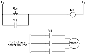
A wiring diagram is a simplified conventional pictorial representation of an electric circuit. Motor contactor wiring diagram pressure online wiring diagram link a permanent live and a neutral from your supply to your coil al a2 then use your switch feed to your photocell from a1 and switch the wire to the switched phase of your contactor load. Contactors help supply motors light systems air conditioners and even large appliances like washers and dryers with electricity. Ladder diagram basics 3 2 wire 3 wire.
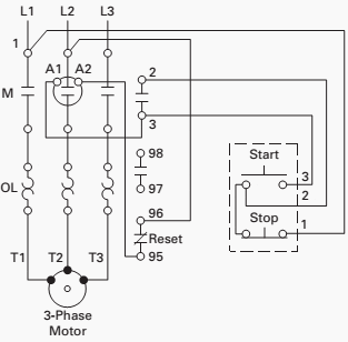
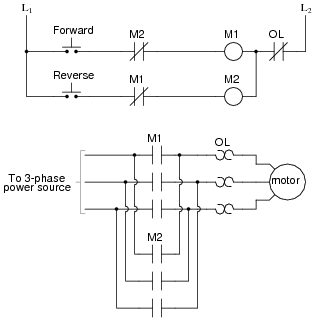
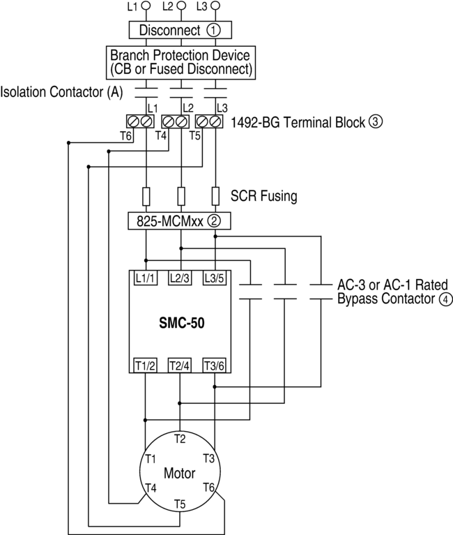
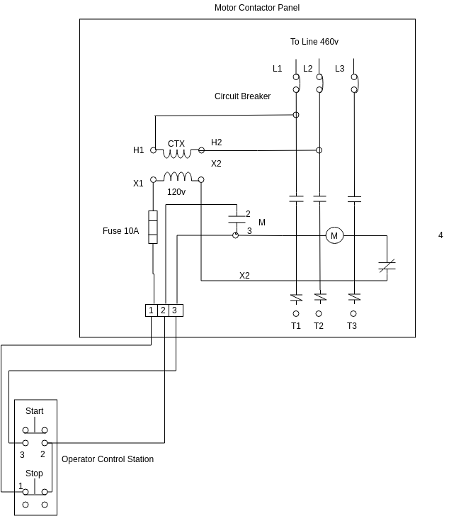
Full voltage reversing 3 phase motors. Wiring diagram for the motor save wiring diagram for single phase. Contactor wiring and i hope after this post you will be able to wire a 3 phase motor i also published a post about 3 phase motor wiring with magnetic contactor and thermal overload relay but today post and contactor wiring diagram is too simple and easy to learn. Wiring diagram for motor contactor best wiring diagram motor fresh.
Assortment of 3 phase motor contactor wiring diagram. You must watch this video. How to wire a contactor and overload direct online starter. A complete guide of single phase induction motor wiring connection with magnetic contactor or stater.
Weg motor starter wiring diagram image. Although wiring a contactor isnt difficult it requires a little bit of electrical know how so call a professional electrician if you need assistance getting the job done. This diagram is for 3 phase reversing motor control with 24 vdc control voltage. The above diagram is a complete method of single phase motor wiring with circuit breaker and contactor.


